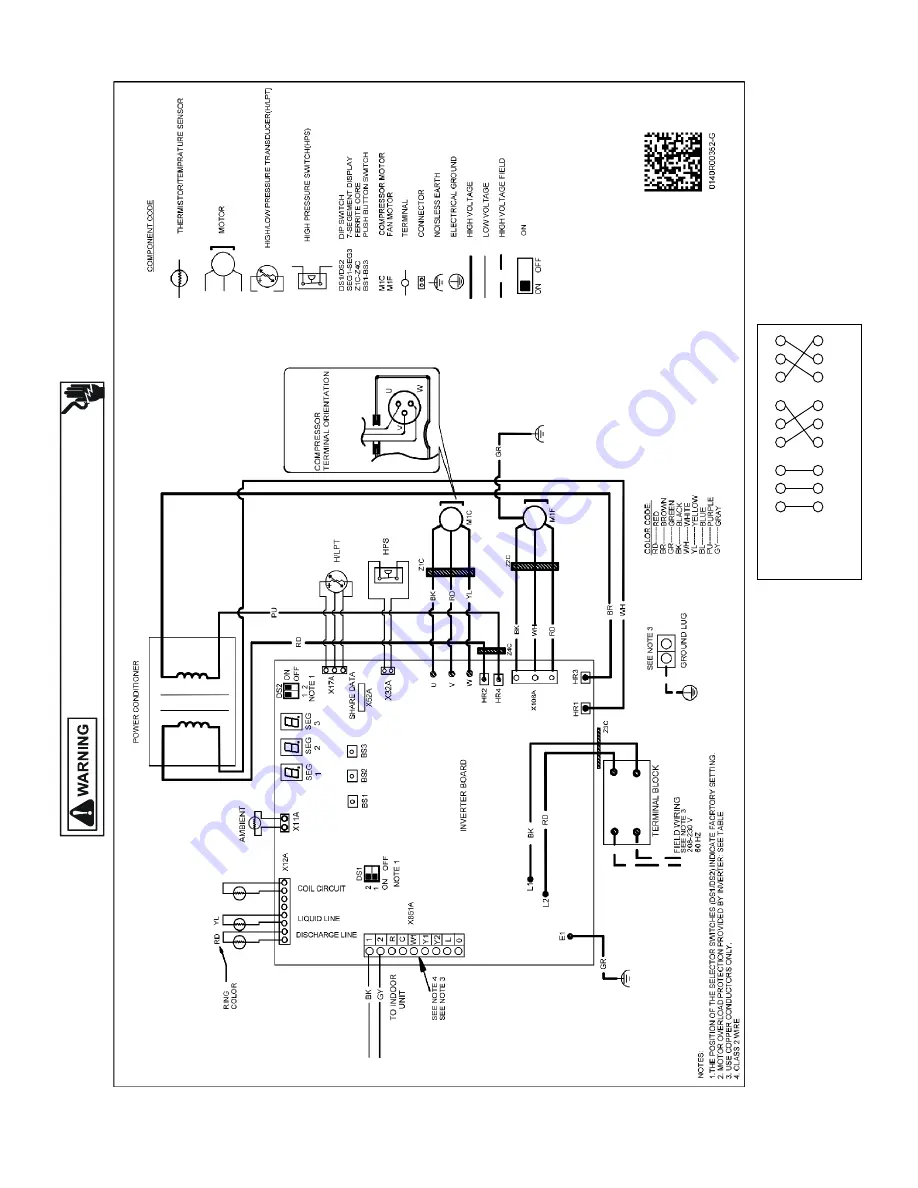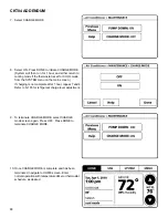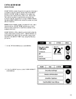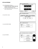
WIRING DIAGRAM
77
HIGH
V
OL
TA
GE
!
DI
SC
ON
NECT
A
LL
P
OW
ER
BEF
ORE
SERVIC
IN
G
OR
INS
TA
LLI
NG
T
HI
S
UNIT
. M
UL
TI
PL
E PO
WE
R SOUR
CES
MA
Y BE P
RESENT
. F
AI
LU
RE
T
O
DO SO
MA
Y CAU
SE
PRO
PE
RT
Y DA
MA
GE,
PERSONAL I
NJ
UR
Y
OR
D
EA
TH
.
Wiring is subject to change. Always refer to the wiring diagram on the unit for the most up-to-date wiring.
N
OTE
:Th
e
compr
essor
can
op
erat
e
normally
in
any
of
th
e
following
wiring
conn
e
c�on
s
shown
on
th
e
right
.
(W
iri
ng
conne
c�on
be
twee
n
co
nt
rol
boa
rd
and
comp
re
ssor
t
erminal
)
U
V
W
U
V
W
U
V
W
U
V
W
W
iri
ng
co
nn
ec
�
on
2
W
iri
ng
co
nn
ec
�
on
3
Co
nt
ro
l B
oa
rd
Te
rm
in
al
si
de
Co
m
pr
ess
or
Te
rm
in
al
si
de
U
V
W
U
V
W
W
iri
ng
co
nn
ec
�
on
1
DX20VC0241**; DX20VC0361**


