SERVICING
20
The thermostat still sends commands to the indoor and out-
door units. However, the thermostat may also request and
receive information from both the indoor and outdoor units.
This information may be displayed on the thermostat.
The indoor and outdoor units also interact with one another.
The outdoor unit may send commands to or request infor-
mation from the indoor unit. This two-way digital commu-
nications between the thermostat and subsystems (indoor/
outdoor unit) and between subsystems is the key to unlock-
ing the benefits and features of the communication system.
Two-way digital communications is accomplished using only
two wires. the thermostat and subsystem controls are pow-
ered with 24 VAC. Thus, a maximum of 4 wires between the
equipment and thermostat is all that is required to operate
the system.
THERMOSTAT WIRING
NOTE
: Only use DAIKIN approved communicating thermo-
stats. Approved communicating thermostats are DAIKIN
ONE+ SMART THERMOSTAT and CTK04AE or newer.
NOTE
: A removable plug connector is provided with the con-
trol board to make thermostat wire connections. Remove the
plug, connect the wires to the plug, and then replace. It is
strongly recommended that you do not connect more than
two wires into a single terminal in the field because there
is a risk of the wires becoming loose, which may result in
intermittent operation.
To wire the system components, it is strongly recommended
to use the same type and same gauge for the wires pre-
pared in the field. (for best results, use 18 AWG.) However,
communications reliability may be improved by using a high
quality, shielded, twisted pair cable for the data transmission
lines. Finally, be sure to confirm that the wires do not come
off each terminal after all connections are finished.
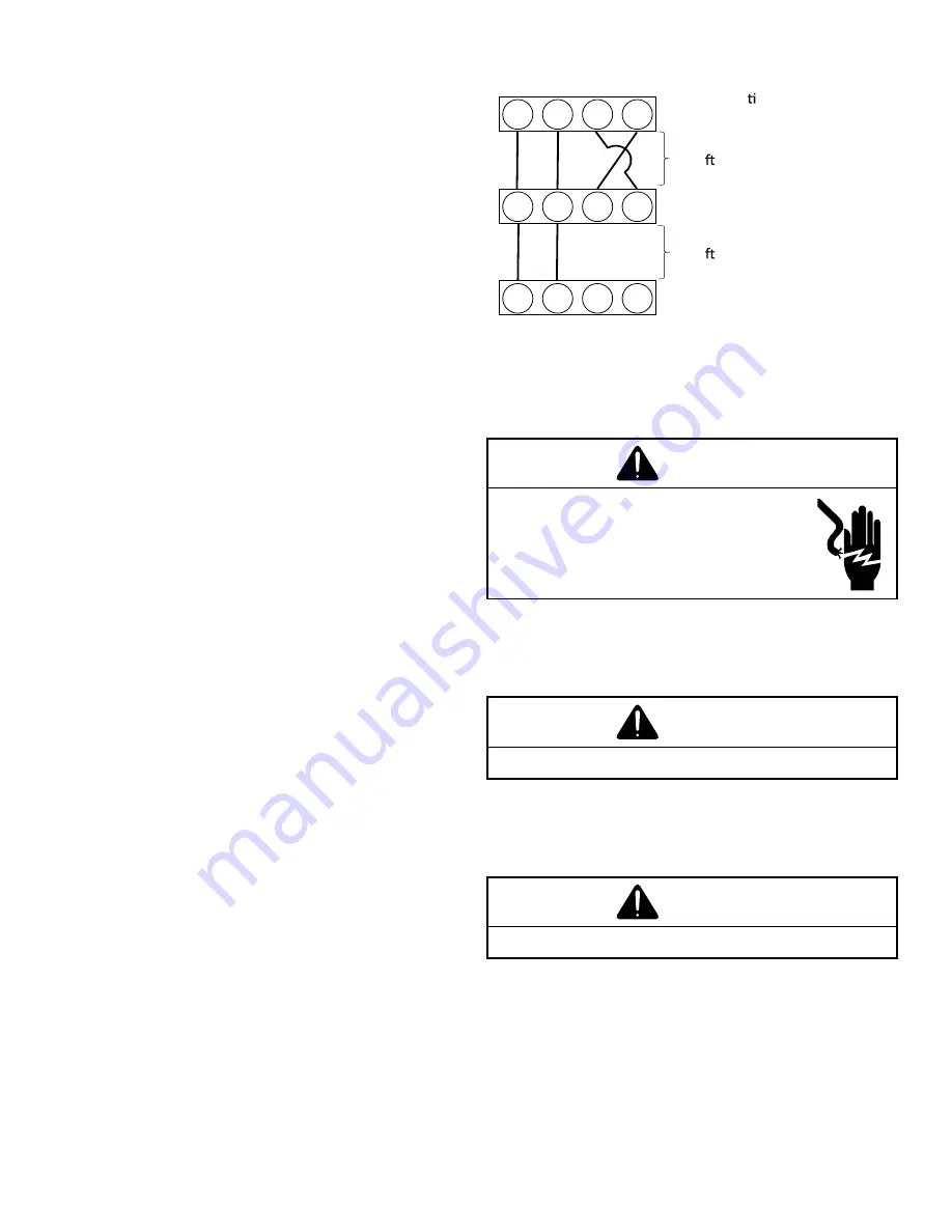
TWO-WIRE OUTDOOR, FOUR-WIRE INDOOR WIRING
Typical wiring will consist of two wires between the indoor
unit and outdoor unit, and four wires between the indoor unit
and thermostat. The figure that follows shows the required
wires: data lines, 1 and 2; R (24 VAC hot) and C (24 VAC
common).
1
2
C
R
1
2
R
C
Air Handler Blower
Gas Furnace or Module Blower
Integrated Control Module
125 . (*)
(*) Allowable Maximum Length
Outdoor unit
Integrated Control Module
250 . (*)
1
2
R
C
Communica ng Thermostat
( In case of
DAIKIN ONE+
SMART THERMOSTAT
)
SYSTEM WIRING
S-4 CHECKING TRANSFORMER AND CONTROL CIRCUIT
WARNING
HIGH VOLTAGE
DISCONNECT ALL POWER BEFORE SERVICING
OR INSTALLING THIS UNIT. MULTIPLE POWER
SOURCES MAY BE PRESENT. FAILURE TO DO SO
MAY CAUSE PROPERTY DAMAGE, PERSONAL IN-
JURY OR DEATH.
A step-down transformer (208/230 or 115 volt primary to 24 volt
secondary) is provided with each indoor unit. This allows ample
capacity for use with resistance heaters. The outdoor sections
do not contain a transformer (see indoor unit Wiring Diagrams).
WARNING
DISCONNECT ALL POWER BEFORE SERVICING.
1. Remove control panel cover, or etc., to gain access to
transformer.
With power ON:
WARNING
LINE VOLTAGE NOW PRESENT.
2. Using a voltmeter, check voltage across secondary volt-
age side of transformer (R to C).
3. No voltage indicates faulty transformer, bad wiring, or
bad splices.
4. Check transformer primary voltage at incoming line volt-
age connections and/or splices.
5. If line voltage available at primary voltage side of trans-
former and wiring and splices good, transformer is inop-
erative. Replace.


