SERVICING
22
B. Shorted - indicator swings to zero and stops there
- replace.
C. Open - no reading - replace. (Start capacitor would
read resistor resistance.)
S-15B CAPACITANCE CHECK (5 TON ONLY)
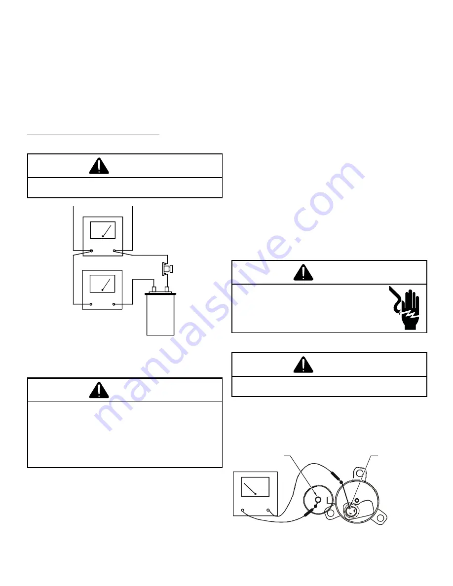
Using a hookup as shown below, take the amperage and
voltage readings and use them in the formula:
Capacitance (MFD) = 2650 X Amperage
Voltage
WARNING
DISCHARGE CAPACITOR THROUGH A 20 TO 30 OHM RESISTOR
BEFORE HANDLING.
VOLTMETER
CAPACITOR
AMMETER
15 AMP
FUSE
TESTING CAPACITANCE
S-17 CHECKING COMPRESSOR
WARNING
HERMETIC COMPRESSOR ELECTRICAL TERMINAL VENTING
CAN BE DANGEROUS. WHEN INSULATING MATERIAL WHICH
SUPPORTS A HERMETIC COMPRESSOR OR ELECTRICAL TER-
MINAL SUDDENLY DISINTEGRATES DUE TO PHYSICAL ABUSE
OR AS A RESULT OF AN ELECTRICAL SHORT BETWEEN THE
TERMINAL AND THE COMPRESSOR HOUSING, THE TERMINAL
MAY BE EXPELLED, VENTING THE VAPOR AND LIQUID CON-
TENTS OF THE COMPRESSOR HOUSING AND SYSTEM.
If the compressor terminal PROTECTIVE COVER and gas-
ket (if required) are not properly in place and secured, there
is a remote possibility if a terminal vents, that the vaporous
and liquid discharge can be ignited, spouting flames several
feet, causing potentially severe or fatal injury to anyone in
its path.
This discharge can be ignited external to the compressor
if the terminal cover is not properly in place and if the dis-
charge impinges on a sufficient heat source.
Ignition of the discharge can also occur at the venting ter-
minal or inside the compressor, if there is sufficient contam
-
inant air present in the system and an electrical arc occurs
as the terminal vents.
Ignition cannot occur at the venting terminal without the
presence of contaminant air, and cannot occur externally
from the venting terminal without the presence of an exter-
nal ignition source.
Therefore, proper evacuation of a hermetic system is essen-
tial at the time of manufacture and during servicing.
To reduce the possibility of external ignition, all open flame,
electrical power, and other heat sources should be extin-
guished or turned off prior to servicing a system.
S-17A RESISTANCE TEST
Inverter on the outdoor control board takes the position
signal from the UVW line connected with the compressor.
When the system detects the malfunction on the compres-
sor, check the insulation resistance in accordance with the
following procedure.
WARNING
HIGH VOLTAGE
DISCONNECT ALL POWER BEFORE SERVICING OR
INSTALLING THIS UNIT. MULTIPLE POWER SOURC-
ES MAY BE PRESENT. FAILURE TO DO SO MAY
CAUSE PROPERTY DAMAGE, PERSONAL INJURY
OR DEATH.
1. Remove the leads from the compressor terminals.
WARNING
SEE WARNINGS S-17 BEFORE REMOVING COMPRESSOR
TERMINAL COVER.
2. Check the wiring connection of UVW on compressor ter-
minal.
3. Check the insulation resistance of compressor between
the compressor terminal and unpainted refrigerant piping.
OHMMETER
Unpainted
Refrigerant
Piping
Compressor
Terminal
TESTING COMPRESSOR WINDINGS


