NOTE
■
M
2
1
2
■
I
M
15 17
16
10 11
1
2
4
5
6
17
10
11
9
Pump operation
With no thermostat connected to the unit (1), the pump (3) can be
configured to operate either as long as the unit is on, or until the
required water temperature is reached.
CAUTION
■
Be sure that the boiler and the integration of the boiler
in the system is in accordance with relevant local laws
and regulations.
Details on pump configuration can be found under
Always install a 3-way valve, even if no domestic hot
"Pump operation configuration" on page 23.
water tank is installed. This to ensure that the freeze
protection function (see "[4-04] Freeze protection
Space heating and cooling
function" on page 28) can operate when the boiler is
active.
According to the season, the customer will select cooling or heating
through the user interface.
The unit (1) will operate in cooling mode or heating mode to achieve
the target leaving water temperature.
1
I
With the unit in heating mode, the 2-way valve (11) is open. Hot water
is provided to both the fan coil units and the floor heating loops.
With the unit in cooling mode, the motorised 2-way valve (11) is
closed to prevent cold water running through the floor heating loops
(FHL).
When closing several loops in the system by remotely
controlled valves, it might be required to install a by-pass
valve (7) to avoid the flow switch safety device from being
activated. See also "Application 2" on page 7.
FHL1 FHL2 FHL3
Wiring of the 2-way valve (11) is different for a NC (normal
Motorised 3-way valve
closed) valve and a NO (normal open) valve! Make sure to
Boiler
connect to the correct terminal numbers as detailed on the
wiring diagram.
Daikin can not be put responsible for incorrect or
unsafe situations in the boiler system.
The ON/OFF setting of the heating/cooling operation is done by the
user interface.
Application 5
1
2
3
4
6
18
17
5
Space heating with an auxiliary boiler (alternating operation)
Space heating application by either the Daikin unit or by an auxiliary
boiler connected in the system. The decision whether either the
E(D/B)* unit or the boiler will operate can be achieved by an auxiliary
contact or an E(D/B)* indoor controlled contact.
The auxiliary contact can e.g. be an outdoor temperature thermostat,
an electricity tariff contact, a manually operated contact, etc. See
"Field wiring configuration A" on page 10.
The E(D/B)* unit controlled contact (also called 'permission signal for
the auxiliary boiler") is determined by the outdoor temperature
(thermistor located at the outdoor unit). See "Field wiring
configuration B" on page 10.
Bivalent operation is only possible for space heating operation,
not
for the domestic water heating operation. Domestic hot water in such
an application is always provided by the domestic hot water tank
which is connected to the Daikin unit.
FHL1
FHL2
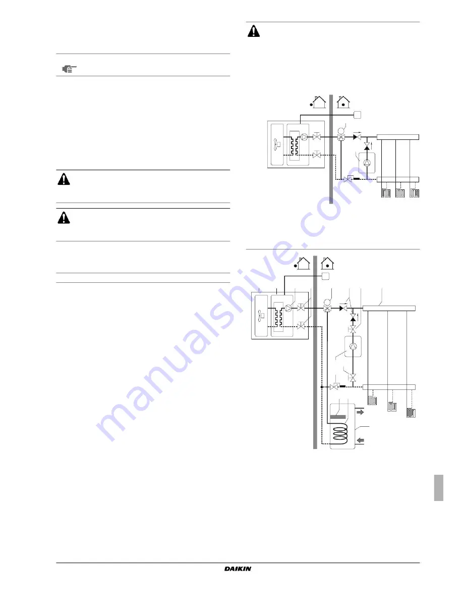
The auxiliary boiler must be integrated in the piping work and in the
field wiring according to the illustrations below.
12
FHL3
Outdoor unit
Heat exchanger
12
Domestic hot water
tank (optional)
3
Pump
Shut-off valve
Collector (field supply)
Motorised 3-way valve
(delivered with the
domestic hot water tank)
Booster heater
Heat exchanger coil
15
15
16
FHL1...3
Boiler (field supply)
Aquastat valve
(field supply)
Shut-off valve
(field supply)
Non-return valve
(field supply)
Floor heating loop
(field supply)
EDLQ036~054B EBLQ036~054BA6VJU1
Installation manual
Unit for air to water heat pump system
4PW56182-1


