EUWN16~ ECB1~3MUW
Packaged water-cooled water chillers
4PW13852-1
Installation manual
3
C
HECKING
THE
WATER
CIRCUIT
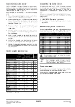
The units are equipped with water inlets and water outlets for connec-
tion to a chilled water circuit and to a hot water circuit. These circuits
must be provided by a licensed technician and must comply with all
relevant European and national regulations.
Before continuing the installation of the unit, check the following
points:
1
A circulation pump must be provided in such a way that it dis-
charges the water directly into the heat exchanger.
2
A flow switch must be installed in the water outlet pipe to prevent
the unit from operating at a water flow which is too low. A
terminal is provided in the switch box for the electrical
connection of the flow switch.
3
A wire mesh strainer (<1 mm) must be installed at the pump
suction as to protect the pump and the heat exchanger from
foreign matter.
4
Drain taps must be provided at all low points of the system to
permit complete drainage of the circuit during maintenance or in
case of shut down.
5
Air vents must be provided at all high points of the system. The
vents should be located at points which are easily accessible for
servicing.
6
Shut-off valves should be provided at the unit so that normal
servicing can be accomplished without draining the system.
7
Vibration eliminators in all water piping connected to the chiller
are recommended to avoid straining the piping and transmitting
vibration and noise.
W
ATER
QUALITY
SPECIFICATIONS
A = corrosion
B = scale
C
ONNECTING
THE
WATER
CIRCUIT
The evaporator and condenser are foreseen of GAS male pipe thread
for the water inlet and outlet (refer to the outlook diagram).
Evaporator and condenser water connections are to be made in
accordance with the outlook diagram, respecting the water in- and
outlet.
If air, moisture or dust gets in the water circuit, problems may occur.
Therefore, always take into account the following when connecting
the water circuit:
1.
Use clean pipes only.
2.
Hold the pipe end downwards when removing burrs.
3.
Cover the pipe end when inserting it through a wall so that no dust
and dirt enter.
W
ATER
CHARGE
,
FLOW
AND
QUALITY
To assure proper operation of the unit a minimum water volume is
required in the system and the water flow through the evaporator
must be within the operation range as specified in the table below.
P
IPING
INSULATION
The complete water circuit, inclusive all piping, must be insulated to
prevent condensation and reduction of the cooling capacity.
Protect the water piping against water freezing during winter period
(e.g. by using a glycol solution or heatertape).
evaporator water
condenser water
circulating
water
[<20°C]
supply
water
circulating
water
[20°C~60°C]
supply
water
tendency
if out of
criteria
Items to be controlled
pH
at 25°C
6.8~8.0
6.8~8.0
7.0~8.0
7.0~8.0
A + B
Electrical
conductivity
[mS/m]
at 25°C
<40
<30
<30
<30
A + B
Chloride ion
[mgCl
-
/l]
<50
<50
<50
<50
A
Sulfate ion
[mgSO
4
2-
/l]
<50
<50
<50
<50
A
M-alkalinity
(pH4.8)
[mgCaCO
3
/l]
<50
<50
<50
<50
B
Total hardness
[mgCaCO
3
/l]
<70
<70
<70
<70
B
Calcium
hardness
[mgCaCO
3
/l]
<50
<50
<50
<50
B
Silica ion
[mgSiO
2
/l]
<30
<30
<30
<30
B
Items to be referred to
Iron
[mgFe/l]
<1.0
<0.3
<1.0
<0.3
A + B
Copper
[mgCu/l]
<1.0
<0.1
<1.0
<0.1
A
Sulfide ion
[mgS
2-
/l]
not detectable
A
Ammonium ion
[mgNH
4
+
/l]
<1.0
<0.1
<0.3
<0.1
A
Remaining
chloride
[mgCl/l]
<0.3
<0.3
<0.25
<0.3
A
Free carbide
[mgCO
2
/l]
<4.0
<4.0
<0.4
<4.0
A
Stability index
—
—
—
—
A + B
Minimum
water volume (l)
Minimum
water flow
Maximum
water flow
16Hp
205
62 l/min
247 l/min
20Hp
268
80 l/min
321 l/min
24Hp
311
93 l/min
373 l/min
32Hp
205
123 l/min
493 l/min
36Hp
268
142 l/min
568 l/min
40Hp
268
161 l/min
642l/min
44Hp
311
173 l/min
694 l/min
48Hp
311
186 l/min
745 l/min
52Hp
205
204 l/min
814 l/min
56Hp
205
222 l/min
889 l/min
60Hp
268
241 l/min
963 l/min
64Hp
268
254 l/min
1015 l/min
68Hp
268
267 l/min
1066 l/min
72Hp
311
280 l/min
1118 l/min
The water pressure should not exceed the maximum
working pressure of 10 bar.
NOTE
Provide adequate safeguards in the water circuit to
make sure that the water pressure will never exceed
the maximum allowable working pressure.
Summary of Contents for ECB1MUW
Page 8: ...NOTES...
Page 25: ...NOTES...
Page 26: ...Zandvoordestraat 300 B 8400 Oostende Belgium 4PWEN13852 1...


