【INSTRUCTION MANUAL】
DAIKIN INDUSTRIES, LTD
.
SE-04430
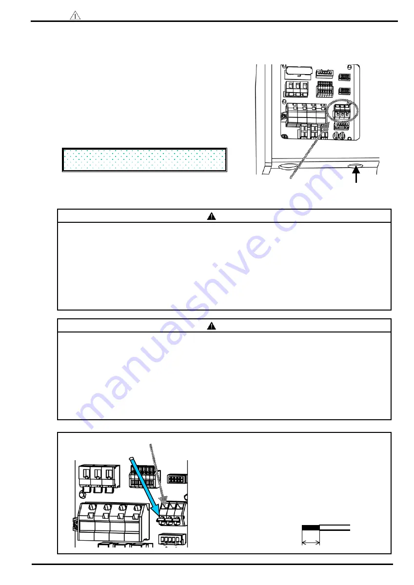
Terminal stand for
alarm signal
Pushing direction of the lever
●
The wiring of alarm signal line-----It is able to transmit the signal of the abnormal condition and operation of the
pressure switch that is outputted from this hydraulic unit.
(The hydraulic unit can be operated without wiring.)
14
(1) Wire the electric cable through the wiring port of the
terminal box. Use the wire and the cable clamp to be
suitable for the wiring port.
[Recommended cable clamp : Laap Co.,Ltd.made ST9]
[screw size : PG9]
(2) Confirm the terminal wiring diagram on the cover of the
terminal box, connect to the alarm signal connection on
the terminal stand for power source.
*This diagram shows power OFF condition.
(alarm condition)
(3) After wiring, be sure to install the cover of the terminal
box as it was.
[COM
-
ALMa] Normal: closed Abnormal: opened
[COM
-
ALMb] Normal: opened Abnormal: closed
Danger
・
Use the electric wire, cab tyre cable with shield which is suitable for AWG22 (0.3sq).
・
Be sure to treat the end of shield cable properly, and ground the one side.
・
Do not connect the alarm connect line to the terminal stand for power source.
・
Be careful not to damage the conductor when stripping electric wire.
・
Use DC24V or DC12V (minimum load-current 10mA) for alarm connection circuit.
Use AC100V (50/60Hz) under alternative current control.
(As for AC200V, it is not able to use in specification of voltage-resistance and insulation distance.)
・
Use it under the maximum load-current less than 1A (load resistance).
・
Be careful not to stick out the conductor of wiring from the terminal stand.
・
As for alarm output signal connect “ALMa” and “COM” of wiring diagram at normal operation.
・
In case of preventing end of the wire from separating, treat its end with solder or use the below mentioned
crimping terminal with insulated sleeve. (Refer to maker’s catalogue “WAGO made” for handling them.)
For AWG22 0.3 sq
:
216-322 light green
For AWG20 0.5 sq
:
216-221 white
Press tool
:
206-204 Bio- crimp (same as for power source)
・
Wiring port is common with control signal. (Terminal stand: WAGO made 256 series)
Caution
Alarm connection
wiring port
Refer to page 12, ”wiring diagram” as for the arrangement of the terminal board.
Wire insert port
①
Push the lever with a driver etc.
②
Make sure of stripped wire length, and insert
them until the end without separating.
③
Remove the driver from the lever.
④
Make sure of wiring by pulling the electric wire
slightly.
How to connect to the terminal stand board
Stripped wire length:6mm
6mm


