【INSTRUCTION MANUAL】
DAIKIN INDUSTRIES, LTD
.
SE-04430
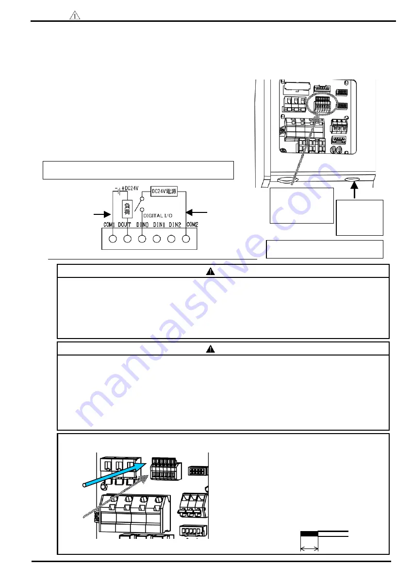
Terminal stand for
operation ready
output signal and
control stop signal
Wiring port for
control
input/output
signal
Wiring diagram of operation ready output signal and control stop signal
15
※
Never connect except between DIN1
and DIN2 terminal.
Danger
・
Use the electric wire, cabtyre cable with shield which is suitable for AWG22 (0.3sq).
・
Be sure to treat the end of shield cable properly, and ground the one side.
・
Do not connect control connect line to the terminal stand for power source.
・
Be careful not to damage the conductor when stripping electric wire.
・
Use DC24V for control stop signal.
・
Be careful not to stick out the conductor of wiring from the terminal stand.
Caution
・
The control stop function is difference in signal input condition (operate/stop) by setting.
(Refer to setting mode of “Operating manual of the control panel”.)
・
At shipping (standard product), when it operates outside switch is “OFF (opened)”, and it stop “ON
(closed)”.
・
The control stop function is standard function for EHU25-L07, EHU25-M07 and EHU30-M07.
・
In case of not connecting well with separating the wire’s end, treat its end with solder.
・
Wiring port is common with alarm signal. (Terminal stand: WAGO made 234 series)
・
When wiring, if the lever is not pushed straight, the terminal stand may be damaged.
①
Push the lever with a driver etc.
②
Make sure of stripped wire length, and insert
them until the end without separating.
③
Remove the driver from the lever.
④
Make sure of wiring by pulling the electric wire
slightly.
How to connect to the terminal stand board
Stripped wire length:6mm
6mm
Pushing direction of the lever
Wire
insert port
●
The wiring of control stop signal line-----It is possible to operate/stop unit by ordering contact input.
(The hydraulic unit can be operated without wiring.)
●
The wiring of operation ready output signal-----It is possible to output operation condition after power on.
After this signal is outputted, start to operate the actuator and so on.
(In case without wiring, refer to “Power supply turning on, a time chart related to alarm”
of attached document B for the time of starting operation of the actuator and so on.)
(1) Wire the electric cable through the wiring port of the terminal box.
Use the wire and the cable clamp to be suitable for the wiring port.
(2) Confirm the terminal wiring diagram on the cover of the terminal box,
connect to the control stop signal connection on the terminal stand for
power source.
Refer to below figure to connect control suspend signal line to
terminal base.
(3) After wiring, be sure to install the cover of the terminal box as it was.
(Wiring port is common with alarm signal.)
※
Wiring of control
stop signal
(It is available either
plus or minus of power
source.)
Refer to page 12, ”wiring diagram” as for the arrangement of
the terminal board.
※
Wiring of operation
ready output signal
(Power source is minus
common.)


