E(D/B)(H/L)Q011~016BB
Unit for air to water heat pump system
4PW67904-1 – 01.2011
Installation manual
16
Important information regarding the refrigerant used
This product contains fluorinated greenhouse gases covered by the
Kyoto Protocol. Do not vent gases into the atmosphere.
Refrigerant type: R410A
GWP
(1)
value: 1975
(1)
GWP = global warming potential
The refrigerant quantity is indicated on the unit name plate
6.4.
Precautions on installation
Foundation work
■
Check the strength and level of the installation ground so that
the unit will not cause any operating vibration or noise after
installation.
■
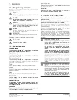
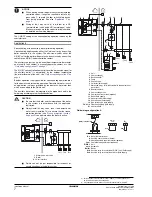
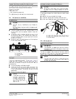
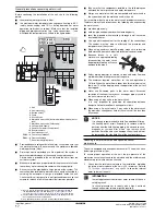
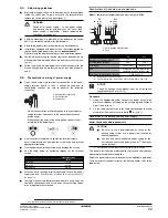
In accordance with the foundation drawing in the figure, fix the
unit securely by means of the foundation bolts. (Prepare four
sets of M12 foundation bolts, nuts and washers each which are
available on the market.)
■
It is best to screw in the foundation bolts until their length are
20 mm from the foundation surface.
A Discharge side
B Bottom view (mm)
C Drain hole
Drain work
Check in the combination table under
"Possible options" on page 3
whether drain work is allowed. In case drain work on your unit is
allowed and the installation site requires drain work, then follow the
guidelines below.
■
Drain kits for drainage are available as option.
■
If drain work from the unit causes trouble (for example, if the
drain water may splash on people) provide the drain piping using
a drain socket (optional) and insulate the pipe to prevent
condensation.
■
Make sure the drain works properly.
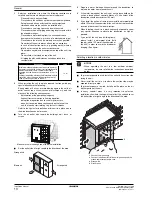
Installation method for prevention of falling over
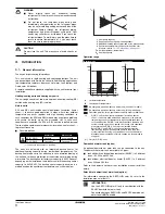
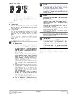
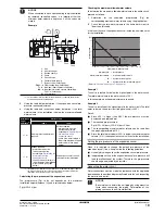
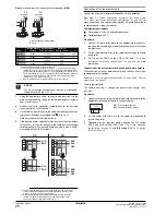
If it is necessary to prevent the unit from falling over, install as shown
in the figure:
■
prepare all 4 wires as indicated in the drawing,
■
unscrew the top plate at the 4 locations indicated A and B,
■
put the screws through the nooses and screw them back tight.
A Location of the 2 fixation holes on the front side of the unit
B Location of the 2 fixation holes on the rear side of the unit
C Wires (field supply)
6.5.
Water pipework
Checking the water circuit
The units are equipped with a water inlet and water outlet for
connection to a water circuit. This circuit must be provided by an
installer and must comply with the applicable legislation.
WARNING
Install the unit on a foundation that can withstand its
weight.
Insufficient strength may result in the fall of equipment and
cause injury.
NOTICE
If drain holes of the unit are
covered by a mounting base
or by floor surface, raise the
unit in order to provide a free
space of more than 100 mm
under the unit.
1435
240
955
240
380
345
20
A
C
C
B
100 mm
CAUTION
Do not allow a child to mount on the unit or avoid placing
any object on the unit. Falling or tumbling may result in
injury.
INFORMATION
If the installation is equipped with a domestic hot water
tank (optional), please refer to the domestic hot water tank
installation manual.
NOTICE
The unit is only to be used in a closed water system.
Application in an open water circuit can lead to excessive
corrosion of the water piping.
C
B
A
A

