Installation manual
27
E(D/B)(H/L)Q011~016BB
Unit for air to water heat pump system
4PW67904-1 – 01.2011
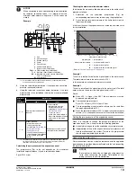
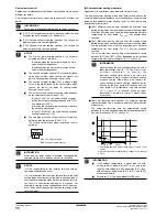
Connect the unit to a normal kWh rate power supply
1
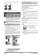
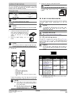
Using the appropriate cable, connect the power supply to the
circuit heater as shown in the wiring diagram and in the figure
below.
1 Earth leakage circuit breaker
2 Fuse
2
Connect the earth conductor (yellow/green) to the earthing
screw.
3
Fix the cable with cable ties to the cable tie mountings to ensure
strain relief.
4
Reconnect the wires according to the figure below.
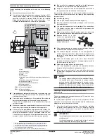
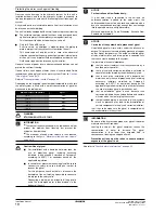
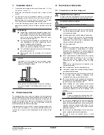
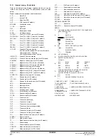
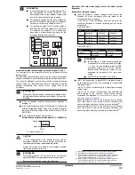
Possible types of benefit kWh rate power supply
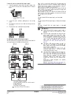
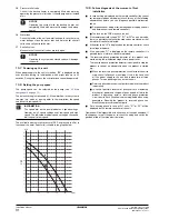
Possible connections and requirements to connect the equipment to
such power supply are illustrated in the figure below:
1 Benefit kWh rate power supply box
2 Receiver controlling the signal of the electricity company
3 Power supply to unit
4 Voltage free contact
5 Normal kWh rate power supply
When the unit is connected to a benefit kWh rate power supply, the
voltage free contact of the receiver controlling the benefit kWh rate
signal of the electricity company must be connected to clamps 17
and 18 of X2M (as illustrated in the figure above).
When parameter [d-01]=1 at the moment that the benefit kWh rate
signal is sent by the electricity company, that contact will open and
the unit will go in forced off mode
(1)
.
When parameter [d-01]=2 at the moment that the benefit kWh rate
signal is sent by the electricity company, that contact will close and
the unit will go in forced off mode
(2)
.
Type 1
This type of benefit kWh rate power supply is not interrupted.
Type 2
This type of benefit kWh rate power supply is interrupted after elapse
of time.
Type 3
This type of benefit kWh rate power supply is interrupted
immediately.
Allowed only for EDL and EBL unit models
4
3
2
1
2
1
N
L
X11M
1
2
1 2 3 4
4
3
2
1
4
3
2
1
2
1
N
L
X11M
4
3
2
1
2
1
N
L
X11M
BLK
WHT
BLK
WHT
4
3
2
1
17 18
1
2
X40A
A1P
L
N
2
4
1
3
3
L
N
2
1
4
3
4
3
L
N
2
1
S2S
S2S
S2S
[d-01]=1
L
N
2
1
3
L
N
2
1
4
3
4
4
4
3
L
N
2
1
S2S
S2S
S2S
[d-01]=2
X11M
X2M
L N
5
(1) When the signal is released again, the voltage free contact will close and
the unit will restart operation. It is therefore important to leave the auto
restart function enabled. Refer to
"[3] Auto restart" on page 34
.
(2) When the signal is released again, the voltage free contact will open and
the unit will restart operation. It is therefore important to leave the auto
restart function enabled. Refer to
"[3] Auto restart" on page 34
.
INFORMATION
■
In case the benefit kWh rate power supply function is
enabled, the screed dry-out function can not be
enabled.
■
When connecting the equipment to a benefit kWh rate
power supply, change field setting [d-01]. When
benefit kWh rate power supply is of type 1 or when the
unit is connected to a normal kWh rate power supply
(via 1-2, X11M) change both field settings [d-01] and
[d-00]. Refer to
"[d]
Benefit kWh rate power
supply/Local shift value weather dependent" on
page 42
.
■
If the benefit kWh rate power supply is of type 1 or
when the unit is connected to a normal kWh rate
power supply, the unit will be forced to off. Controlling
the solar pump is still possible.
When the benefit kWh rate signal is sent, the
centralised control indicator
e
will flash to indicate
that the benefit kWh rate is active.
■
If the benefit kWh rate power supply is of type 2 or 3
and the unit is not connected to a normal kWh rate
power supply, then the backup heater and booster
heater cannot be controlled. This power supply
interruption should not be longer than 2 hours,
otherwise the real time clock of the controller will be
reset.
During power supply interruption, the controller
display will be blank.
Refer to
"For a benefit kWh rate power supply like
illustrated below as types 2 or 3" on page 26
.

