Installation manual
31
E(D/B)(H/L)Q011~016BB
Unit for air to water heat pump system
4PW67904-1 – 01.2011
15
Pressure relief valve
Check if the backup heater is completely filled with water by
operating the pressure relief valve. It should purge water instead
of air.
16
Water leak
Check the inside of the unit on water leakage. in case there is a
water leakage close the water inlet and water outlet shut-off
valves and call your local dealer.
17
Shut-off valves
Make sure that the shut-off valves are fully open.
10.7. Powering up the unit
When power supply to the unit is turned on, "
88
" is displayed on the
user interface during its initialisation, which might take up to 30
seconds. During this process the user interface cannot be operated.
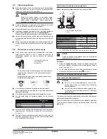
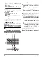
10.8. Setting the pump speed
The pump speed can be selected on the pump (see
"5.2. Main
components" on page 10
).
The default setting is high speed (I). If the water flow in the system is
too high (e.g., noise of running water in the installation) the speed
can be set to low speed (II).
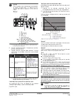
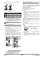
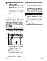
The available external static pressure (ESP, expressed in kPa) in
function of the water flow (l/min) is shown in the graph below.
10.9. Failure diagnosis at the moment of first
installation
■
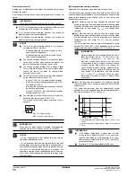
In case nothing is displayed on the remote controller (the current
set temperature does not display), check for any of the following
abnormalities before you can diagnose possible malfunction
codes.
■
Disconnection or wiring error (between power supply and unit
and between unit and remote controller).
■
The fuse on the PCB may have run out.
■
If the remote controller shows "
E3
", "
E4
" or "
L8
" as an error code,
there is a possibility that either the stop valves are closed, or that
air inlet or air outlet are blocked.
■
If the error code "
U2
" is displayed on the remote controller, check
for voltage imbalance.
■
If the error code
"L4"
is displayed on the remote controller, it is
possible that air inlet or air outlet are blocked.
■
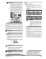
The reversed phase protection detector of this product only
works during the initialisation stage after a power reset.
The reversed phase protection detector is designed to stop the
product in case of an abnormality when the product is started
up.
■
When the reversed phase protection circuit forced the unit to
stop, check if all phases are existing. If this is the case, shut
off the power supply to the unit and replace two of three
phases. Turn on power again and start the unit.
■
Reversed phase detection is not performed while the product
is operating.
■
In case of possible reversal of phases after a momentary
black out of power and the power goes on and off while the
product is operating, install a reversed phase protection
circuit on site. Such situation is not unimaginable when using
generators. Running the product in reversed phase can
break the compressor and other parts.
■
For a missing phase in case of W1 units, "
E7
" or "
U2
" will be
displayed on the remote controller of the unit.
Operation will be impossible with either one of these phenomena. If
this happens, turn off the power, re-check the wiring and switch the
position of two of the three electrical wires.
NOTICE
Operating the system with the backup heater not
completely filled with water will damage the backup
heater!
NOTICE
Operating the system with closed valves will damage
the pump!
INFORMATION
The speed dial on the pump indicates 3 speed settings.
However, only 2 speed settings exist: low speed and high
speed. The indicated medium speed setting on the speed
dial is equal to low speed.
0
5
10
15
20
30
40
45
55
60
65
75
80
85
ESP
[l/min]
[kPa]
20
30
40
50
16
60
25
35
50
70

