background image

Installation manual

49

E(D/B)(H/L)Q011~016BB

Unit for air to water heat pump system

4PW67904-1 – 01.2011

11.5. Underfloor heating screed dry-out program

This function allows the installer to define and automatically execute
an "underfloor heating screed dry-out" program.

The program is used to dry-out the screed of an underfloor heating
during the construction of a house.

Disclaimer

1.

Even though the program will execute automatically the different
programmed actions, the installer is responsible to check on
regular basis the good working of the setup.

2.

Please pay attention that the installer has full responsibility to
select the correct program that fits to the type of used screed for
the floor.

Field settings

Underfloor screed dry-out field settings:

[F-05] Action number selection

[F-06] Heating set point of selected action number [F-05]

[F-07] Time of selected action number [F-05] (steps of 12 hours)

[F-08] Underfloor heating screed dry-out program enabled
(1)/disabled (0)

[F-09] (Read only) Latest action number executed.

In case "underfloor heating screed dry-out program" is executed
successful then [F-09] has value 21.

Getting started

Each action is executed with a programmed heating set point for
a programmed time (steps of 12 hours).

A maximum of 20 different actions can be programmed.

The program is activated in the test run operation.

When the program is stopped by an error or an operation switch
off or a power failure, the 

U3

 error code will be displayed.

To resolve the error codes, see 

"13.3. Error codes" on page 53

.

Procedure

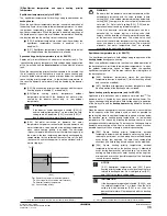
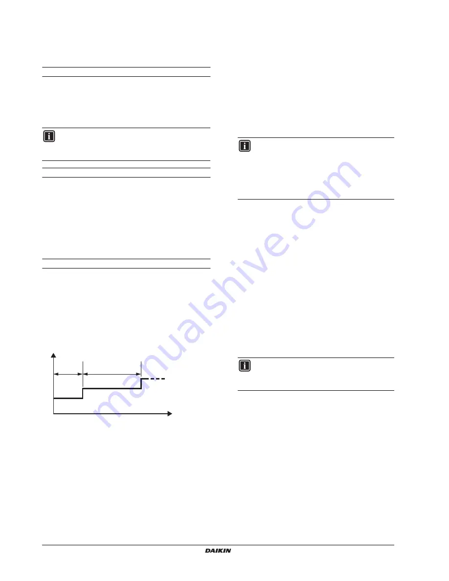
Example of program:

Heating set point

Time

(1) Action number 1
(2) Action number 2

1

Set field settings

The different actions are programmed as follows:
(refer to 

"10.10. Field settings" on page 32

  to know how to

change the field settings)

Set in [F-05] (Action number), the action to be programmed,

example 1.
Save the new value by pressing the 

pr

 button.

Set in [F-06] (Heating set point of selected action number

[F-05]), example 25°C.
Save the new value by pressing the 

pr

 button.

Set in [F-07] (Time of selected action number [F-05]),

example 24 hours.
Save the new value by pressing the 

pr

 button.

Repeat step 1 through 3 to program all the actions.

Consult the different actions to confirm good setting values
as follows:
(Refer to 

"10.10. Field settings" on page 32

  to know how to

change the field settings)

Set in [F-05] (Action number), the action to be consulted,

example 1.
Save the new value by pressing the 

pr

 button.

Consult [F-06] (Heating set point of selected number [F-05])

Consult [F-07] (Time of selected number [F-05]), example 24

hours.

Repeat step 1 through 3 to consult all the actions.

Enable the "underfloor heating screed dry-out program" as
follows:

Set in [F-08] (Underfloor heating screed dry-out program

enabled/disabled) to 1 (enabled).

When finished, press the 

z

  button to exit the FIELD SET

MODE.

2

Activate

Push the 

z

  button 4 times so the 

t

  icon will be

displayed.

To  start the "Underfloor heating dry-out program" press the

y

 button.

The "Underfloor heating dry-out program" will start and

display the action and temperature setting of action
number 1. The icon 

e

 is also displayed.

3

During activation

The underfloor heating dry-out program will automatically run
through all programmed actions.

4

End

When all actions are executed, the program will automatically

be stopped by switching off the unit and the 

t

 icon will be

disappeared.

When the (Underfloor heating dry-out program) has ended

successfully the [F-09] will have value 21.

INFORMATION

Benefit kWh rate power supply cannot be used in
combination with "underfloor heating screed dry-out
program". (In case [d-01] is enabled, [F-08] can not be set.)

[F-07]=24 h

[F-07]=48 h

[F-06]=25

°

C

[F-06]=35

°

C

(1)

(2)

(1)

(2)

t

H

INFORMATION

The not set actions will not be programmed
because these actions has time [F-07] equal to 0
hours as default.

So in case too many actions are programmed
and the quantity needs to be reduced, set the
time [F-07] to 0 hours of the actions that don’t
need to be executed.

INFORMATION

The activation of the "Underfloor heating screed
dry-out program" is similar to the starting the Test run
operation

Summary of Contents for EDHQ011BB6V3

Page 1: ...EDHQ016BB6W1 EDLQ011BB6V3 EDLQ014BB6V3 EDLQ016BB6V3 EDLQ011BB6W1 EDLQ014BB6W1 EDLQ016BB6W1 EBHQ011BB6V3 EBHQ014BB6V3 EBHQ016BB6V3 EBHQ011BB6W1 EBHQ014BB6W1 EBHQ016BB6W1 EBLQ011BB6V3 EBLQ014BB6V3 EBLQ0...

Page 2: ...2 1 W1 V3 DC AC DC AC AC AC A A B1 B1 B1 B2 B2 B2 C C D1 D1 D1 D2 D2 D2 D2 D2 E E H H L1 L1 L1 L2 L2 L2 1 1 2 A A B2 B2 B2 D1 D1 D1 D2 D2 D2 D2 D2 E E H H L1 L1 L1 L2 L2 L2 B1 B1 B1 C C 1 2...

Page 3: ...gelse af bestemmelserne i 11 enligt villkoren i 12 gitt i henhold til bestemmelsene i 13 noudattaen m r yksi 14 za dodr en ustanoven p edpisu 15 prema odredbama 16 k veti a z 17 zgodnie z postanowieni...

Page 4: ...lines 24 9 5 Precautions on wiring of power supply 24 Specifications of standard wiring components 24 Connection of the backup heater power supply 24 Connection of the thermostat cable 25 Connection o...

Page 5: ...eration of the unit always contact your local dealer for advice and information Improper installation or attachment of equipment or accessories could result in electric shock short circuit leaks fire...

Page 6: ...trical booster heater EKHW in 3 different sizes 150 200 and 300 litre tank without electrical booster heater EKHTS in 2 different sizes 200 and 260 litre Refer to the domestic hot water tank installat...

Page 7: ...e the selection is done and the water system is designed this manual describes the procedures for handling installing and connecting the EDH EBH EDL and EBL units This manual has been prepared to ensu...

Page 8: ...s on pump configuration can be found under 10 3 Pump operation configuration on page 29 NOTICE When circulation in each floor heating loop FHL1 3 is controlled by remotely controlled valves M1 3 it is...

Page 9: ...ugh floor heating loops and fan coil units Cooling is provided through the fan coil units only 1 Unit 2 Heat exchanger 3 Backup heater 4 Pump 5 Shut off valve 6 Collector field supply 7 By pass valve...

Page 10: ...12 Aquastat valve field supply 13 Shut off valve field supply 14 Non return valve field supply FHL1 3 Floor heating loop field supply UI User interface Field wiring configuration A BTI Boiler thermost...

Page 11: ...as to achieve the target leaving water temperature as set on the user interface When weather dependent operation is active the water temperature is determined automatically depending on the outdoor t...

Page 12: ...s that the heat pump will can operate at the lowest required leaving water temperature when only floor heating is required Higher leaving water temperatures are only required in case fan coil units ar...

Page 13: ...t 4 Heat exchanger 5 Expansion vessel 10 l 6 Refrigerant liquid connection 7 Refrigerant gas connection 8 Shut off valves The shut off valves on the water inlet connection and water outlet connection...

Page 14: ...h box main components door 2 1 Backup heater contactors K1M and K5M 2 Main PCB The main PCB Printed Circuit Board controls the functioning of the unit 3 Booster heater contactor K3M only for installat...

Page 15: ...mals making contact with electrical parts can cause malfunctions smoke or fire Please instruct the customer to keep the area around the unit clean and clear Carry out the specified installation work i...

Page 16: ...ion of the wind 3 Prepare a water drainage channel around the foundation to drain waste water from around the unit 4 If the water drainage of the unit is not easy please build up the unit on a foundat...

Page 17: ...ge 16 Precaution A In case of non stacked installation figure 1 INFORMATION Spare thermistor fixing plate is delivered in the accessory bag 2 1 3 4 5 6 8 7 9 10 Suction side obstacle Obstacle is prese...

Page 18: ...slings These slings can be fitted into specially for this purpose foreseen sleeves at the base frame Opening closing the unit Be sure to confirm the model name and the serial no of the outer front pla...

Page 19: ...tional and insulate the pipe to prevent condensation Make sure the drain works properly Installation method for prevention of falling over If it is necessary to prevent the unit from falling over inst...

Page 20: ...ss metallic piping make sure to insulate both materials from each other to prevent galvanic corrosion Because brass is a soft material use appropriate tooling for connecting the water circuit Inapprop...

Page 21: ...ll lead to malfunction of the system Therefore the pre pressure should only be adjusted by an installer Connecting the water circuit Water connections must be made in accordance with the applicable le...

Page 22: ...applicable legislation In case of over pressure when using glycol be sure to connect the safety valve to a drain pan in order to recover the glycol For this purpose a knock out hole is foreseen in the...

Page 23: ...very likely to happen and damaging the system in the process A A WARNING Electrical installation All field wiring and components must be installed by an installer and must comply with the applicable l...

Page 24: ...n PS Switching power supply Q1DI Earth leakage circuit breaker R1 R2 Resistor only for V3 models R1 R4 Resistor only for W1 models R1T Thermistor air R2T Thermistor discharge R3T Thermistor suction R4...

Page 25: ...WIRING DIAGRAM ONLY APPLIES TO THE HYDROMODULE SWITCH BOX 2 USE A DEDICATED POWER CIRCUIT FOR THE BACKUP HEATER AND BOOSTER HEATER NEVER USE A POWER CIRCUIT SHARED BY OTHER APPLIANCE 3 FIELD WIRING NO...

Page 26: ...ooster heater EKHW T M M B 1 2 6 4 12 5 7 8 9 C D F I J H G UI E 3 A K 10 11 Item Description AC DC Required number of conductors Maximum running current 1 Power supply cable for unit AC 2 GND a a Ref...

Page 27: ...te connections and fix the wires so that outside forces are not applied to the terminals Specifications of standard wiring components Door 1 compressor compartment and electrical parts X1M 1 Earth lea...

Page 28: ...shall be a voltage free contact that ensure 230 V 100 mA Procedure 1 Connect the contact of first set point and second set point to the appropriate terminals as shown in the figure below 2 Fix the ca...

Page 29: ...3 way valve The 3 way valve should be fitted as such that when the 3 way valve is idle not activated the space heating circuit is selected SPST 3 wire type 3 way valve The 3 way valve should be fitted...

Page 30: ...2 1 N L X11M 1 2 1 2 3 4 4 3 2 1 4 3 2 1 2 1 N L X11M 4 3 2 1 2 1 N L X11M BLK WHT BLK WHT 4 3 2 1 17 18 1 2 X40A A1P L N 2 4 1 3 3 L N 2 1 4 3 4 3 L N 2 1 S2S S2S S2S d 01 1 L N 2 1 3 L N 2 1 4 3 4 4...

Page 31: ...75 1 25 mm2 Maximum length 500 m NOTICE The wiring for connection is not included NOTICE The digital controller delivered in a kit has to be mounted indoors NOTICE Be careful not to distort the shape...

Page 32: ...e lifetime of the pump INFORMATION When a room thermostat is connected to the unit the heating and cooling schedule timers are never available Other schedule timers are not affected For more informati...

Page 33: ...B 1 Do not forget to turn on the booster heater circuit breaker F2B in the switch box applies only to units with optional domestic hot water tank 6 Earth wiring Make sure that the earth wires have bee...

Page 34: ...or air outlet are blocked If the error code U2 is displayed on the remote controller check for voltage imbalance If the error code L4 is displayed on the remote controller it is possible that air inl...

Page 35: ...ication on the user interface is given When level 2 3 is selected the actual permission level either level 2 or level 3 is determined by the field setting 0 00 1 Weather dependent set point The weathe...

Page 36: ...h the domestic hot water should be heated 2 01 Status defines whether the disinfection function is turned on 1 or off 0 2 02 Start time time of the day at which the domestic hot water should be heated...

Page 37: ...operation is only allowed if heat pump is out of operation range of heat pump domestic water heating mode TA 5 03 or TA 35 C or domestic hot water temperature is 2 C lower then the heat pump OFF tempe...

Page 38: ...n is enabled and permission signal for auxiliary boiler is ON the booster heater will be restricted even when TA 5 03 See C 02 on page 41 Booster heater is always allowed during powerful and disinfect...

Page 39: ...and can not be modified 5 01 Equilibrium temperature outdoor temperature below which operation of the backup heater is allowed Space heating priority temperature only for EKHTS Applies only to instal...

Page 40: ...Example 1 Scheduled storage 6 03 1 scheduled reheat 6 05 1 disinfection function 2 01 1 activated A Scheduled storage operation activated at 6 04 heat up domestic hot water untill domestic hot water u...

Page 41: ...e domestic hot water set point is according to your requirements Start with a low domestic hot water storage set point and only increase if you feel that the domestic hot water supply temperature is n...

Page 42: ...t set point can be a fixed value or weather dependent The second set point heating 7 03 should be linked to the heat emitters which require the highest set point in heating mode Example fan coil units...

Page 43: ...pplicable in heating mode INFORMATION When heat pump is active in domestic water heating mode the delay time of booster heater is 8 03 When heat pump is not active in domestic water heating mode the d...

Page 44: ...ting operation parallel connected The purpose of this function is to determine based on the outdoor temperature which heating source can will provide the space heating either the Daikin unit or an aux...

Page 45: ...unit is not single phase W1 the combination of setting 4 03 0 2 with bivalent operation at low outdoor temperature can result in domestic hot water shortage The bivalent operation function has no impa...

Page 46: ...disabled 0 Space cooling permission F 01 Space cooling permission temperature defines the outdoor temperature below which space cooling is turned off Bottom plate heater control Applies only to insta...

Page 47: ...3 5 60 fixed 5 C 03 Set point only in combination with domestic hot water tank with built in electrical booster heater EKHW 4 03 5 70 55 80 5 C 04 Interval only in combination with domestic hot water...

Page 48: ...ed time storage start time 1 00 0 00 23 00 1 00 hour 05 Scheduled time reheat or continuous reheat 0 OFF 0 1 2 1 06 Scheduled time reheat start time 15 00 0 00 23 00 1 00 hour 07 Domestic hot water re...

Page 49: ...pplicable Do not change the default value 0 Read only C Setup on EKRP1HB digital I O PCB 00 Solar priority mode setting 0 0 1 1 01 Alarm output logic 0 0 1 1 02 X1 X2 function Bivalent operation statu...

Page 50: ...on number selection 1 1 20 1 06 Heating set point of selected action number F 05 25 0 c 15 55 1 C 07 Time of selected action number F 05 0 c 0 72 12 hour 08 Underfloor heating screed dry out program e...

Page 51: ...st the cooling operation push the h c button so the c icon is displayed To start the test run operation press the y button To test the domestic water heating operation push the v button The test run o...
Page 52: ...xample 25 C Save the new value by pressing the pr button 3 Set in F 07 Time of selected action number F 05 example 24 hours Save the new value by pressing the pr button 4 Repeat step 1 through 3 to pr...

Page 53: ...program enabled 1 disabled 0 is always set to 0 disable when a program has been started once This means that in case a second time an underfloor heating screed dry out program must be started then F 0...

Page 54: ...f NOTICE For problems related to the optional solar kit for domestic water heating refer to the troubleshooting in the installation manual of that kit POSSIBLE CAUSES CORRECTIVE ACTION The temperature...

Page 55: ...ted Check that the backup heater operation status field setting 4 00 is turned on see 10 10 Field settings on page 32 Check whether or not the thermal protector of the backup heater has been activated...

Page 56: ...is giving the correct read out A1 Hydraulic PCB defective Contact your local dealer A5 Too high during heating operation or too low during cooling operation refrigerant temperature measured by R13T C...

Page 57: ...contain the latest action number executed F 08 Underfloor heating screed dry out program enabled 1 disabled 0 is always cleared to 0 disable This means that in case a second time a Underfloor heating...

Page 58: ......

Page 59: ......

Page 60: ...4PW67904 1 01 2011 Copyright 2011 Daikin...

Reviews: