12 Troubleshooting
Installer reference guide
83
ERGA04~08DAV3(A) + EHVH/X04+08S18+23DA
Daikin Altherma – Low temperature split
4P495248-1 – 2017.12
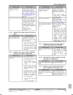
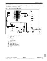
a
b
a
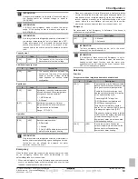
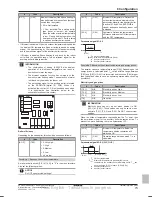
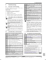
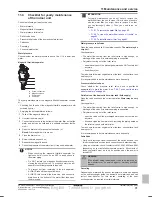
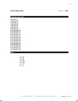
Bottom part to be unscrewed
b
Water filter housing
3
Remove the strainer and the rolled‑up filter from the water filter
housing and clean with water.
4
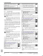
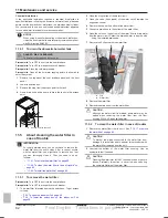
Install the cleaned rolled‑up filter and strainer in the water filter
housing.
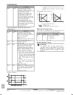
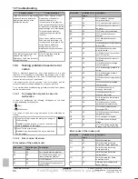
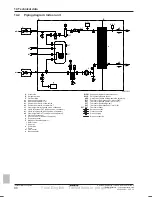
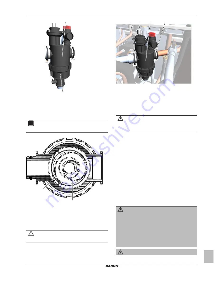
INFORMATION
Correctly install the strainer in the water filter housing using
the protrusions.
a
b
c
c
a
Rolled‑up filter
b
Strainer
c
Protrusion
5
Install and properly tighten the bottom of the water filter
housing.
11.5.3
To install the water filter
CAUTION
Check the condition of the O-rings and replace if needed.
Apply water to the O-rings before installation.
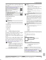
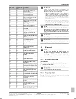
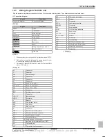
1
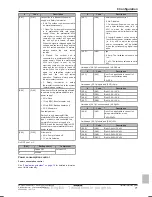
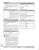
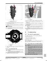
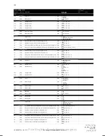
Install the water filter in the correct location.
a
a
b
c
a
Clip
b
Water filter
c
Air purge valve
2
Install the 2 clips to fix the water filter to the water circuit pipes.
3
Make sure that the air purge valve of the water filter is in the
open position.
4
Open the valve (if equipped) of the water circuit towards the
expansion vessel.
CAUTION
Make sure to open the valve (if equipped) towards the
expansion vessel, otherwise the overpressure will be
generated.
5
Open the stop valves and add water to the water circuit if
needed.
12
Troubleshooting
12.1
Overview: Troubleshooting
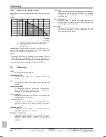
This chapter describes what you have to do in case of problems.
It contains information about:
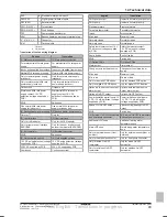
▪ Solving problems based on symptoms
▪ Solving problems based on error codes
Before troubleshooting
Carry out a thorough visual inspection of the unit and look for
obvious defects such as loose connections or defective wiring.
12.2
Precautions when troubleshooting
WARNING
▪ When carrying out an inspection on the switch box of
the unit, ALWAYS make sure that the unit is
disconnected from the mains. Turn off the respective
circuit breaker.
▪ When a safety device was activated, stop the unit and
find out why the safety device was activated before
resetting it. NEVER bridge safety devices or change
their values to a value other than the factory default
setting. If you are unable to find the cause of the
problem, call your dealer.
DANGER: RISK OF ELECTROCUTION
Final English - Tanslations in progress


