background image

EKHBH/X008BB

Indoor unit for air to water heat pump system

4PW62570-1A – 01.2011

Installation manual

50

12. T

ECHNICAL


SPECIFICATIONS

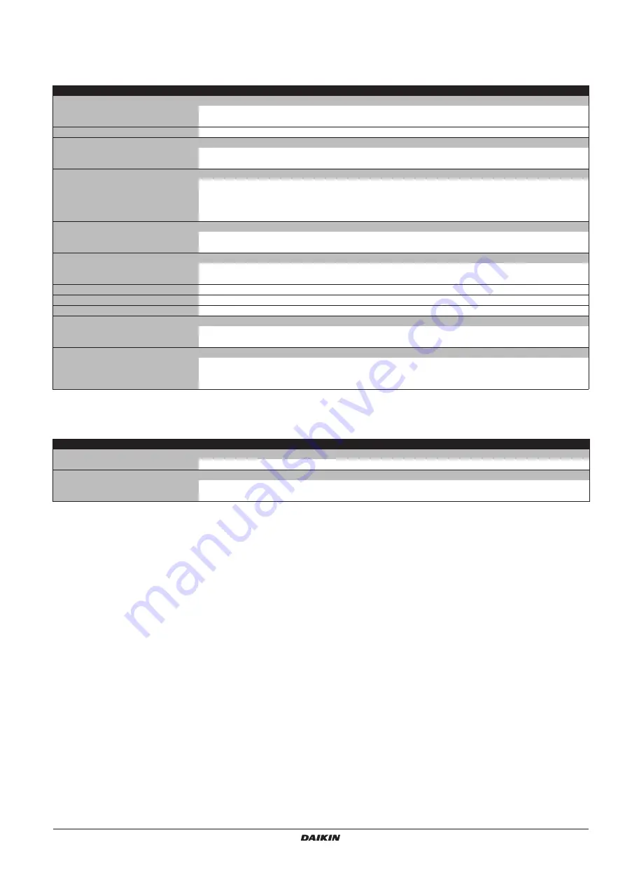
12.1. General

12.2. Electrical specifications

Heating/cooling models (EKHBX) 

Heating only models (EKHBH)

Nominal capacity

• cooling

Refer to the Technical Data

• heating

Refer to the Technical Data

Dimensions H x W x D

922 x 502 x 361

922 x 502 x 361

Weight

• machine weight

46 kg

46 kg

• operation weight

59 kg

59 kg

Connections

• water inlet/outlet

1" MBSP

(a)

(a) MBSP = Male British Standard Pipe

1" MBSP

(a)

• water drain

hose nipple

hose nipple

• refrigerant liquid side

Ø6.4 mm (1/4 inch)

Ø6.4 mm (1/4 inch)

• refrigerant gas side

Ø15.9 mm (5/8 inch)

Ø15.9 mm (5/8 inch)

Expansion vessel

• volume

10 l

10 l

• maximum working pressure (MWP)

3 bar

3 bar

Pump

• type

water cooled

water cooled

• no. of speed

3

3

Sound pressure level

Refer to technical data

Refer to technical data

Internal water volume

5.5 l

5.5 l

Pressure relief valve water circuit

3 bar

3 bar

Operation range - water side

• heating

+15~+50°C

+15~+50°C

• cooling

+5~+22°C

Operation range - air side

• heating

–20~+25°C

–20~+25°C

• cooling

+10~+43°C

• domestic hot water by heat pump

–15~+35°C

–15~+35°C

Heating/cooling models (EKHBX)

Heating only models (EKHBH)

Standard unit (power supply via outdoor unit)

• power supply

230 V 50 Hz 1P

Backup heater

• power supply

See 

"Connection of the backup heater power supply" on page 20

• maximum running current

See 

"Connection of the backup heater power supply" on page 20

Summary of Contents for EKHBH-BB

Page 1: ...EKHBH008BB EKHBX008BB Indoor unit for air to water heat pump system EKHBH008BB3V3 EKHBH008BB6V3 EKHBH008BB6WN EKHBH008BB6T1 EKHBH008BB9WN EKHBH008BB9T1 EKHBX008BB3V3 EKHBX008BB6V3 EKHBX008BB6WN EKHBX008BB6T1 EKHBX008BB9WN ...

Page 2: ...90 30 3 4 35 48 142 101 502 2 3 4 5 48 39 96 361 1 1 2 MBSP 1 MBSP 895 922 830 469 260 B B T T 2 350 300 500 1 2x 2x 1x 1x 1x 1 2 3 4 5 1 2 3 4 ...

Page 3: ... ͈v Ùˆv 08 de acordo com o previsto em 09 в соответствии с положениями 10 under iagttagelse af bestemmelserne i 11 enligt villkoren i 12 gitt i henhold til bestemmelsene i 13 noudattaen määräyksiä 14 za dodržení ustanovení předpisu 15 prema odredbama 16 követi a z 17 zgodnie z postanowieniami Dyrektyw 18 în urma prevederilor 19 ob upoštevanju določb 20 vastavalt nõuetele 21 следвайки клаузите на...

Page 4: ...3 8 2 Room thermostat installation configuration 24 8 3 Pump operation configuration 24 8 4 Domestic hot water tank installation configuration 25 8 5 Initial start up at low outdoor ambient temperatures 25 8 6 Pre operation checks 25 Checks before initial start up 25 8 7 Powering up the indoor unit 26 8 8 Setting the pump speed 26 8 9 Field settings 26 Procedure 26 Detailed description 27 8 10 Fie...

Page 5: ...peration of the unit always contact your local dealer for advice and information Improper installation or attachment of equipment or accessories could result in electric shock short circuit leaks fire or other damage to the equipment Be sure only to use accessories and optional equipment made by Daikin which are specially designed for use with the products as of subject in this manual and have the...

Page 6: ...heater 4 Equilibriumtemperature can be set through the user interface refer to 8 9 Field settings on page 26 TA Ambient outdoor temperature PH Heating capacity Domestic hot water tank option 2 An optional domestic hot water tank can be connected to the indoor unit The domestic hot water tank is available in 2 types tank with built in electrical booster heater EKHW in 3 different sizes 150 200 and ...

Page 7: ...s interrupted Refer to Connection to a benefit kWh rate power supply on page 22 for more details 3 2 Scope of this manual This manual does NOT include the selection procedure and the water system design procedure Only some precautions and tips and tricks about the design of the water circuit are given in a separate chapter of this manual Once the selection is done and the water system is designed ...

Page 8: ...il FHL1 3 Floor heating loop T1 3 Individual room thermostat optional M1 3 Individual motorised valve to control the floor heating loop field supply Pump operation With no thermostat connected to the indoor unit 2 the pump 5 can be configured to operate either as long as the indoor unit is on or until the required water temperature is reached Space heating The outdoor unit 1 will operate to achiev...

Page 9: ...he pump will start operating and the indoor unit 2 will switch to heating mode cooling mode The outdoor unit 1 will start operating to achieve the target leaving hot cold water temperature In case of cooling mode the 2 way valve 8 will close as to prevent cold water running through the floor heating loops FHL 1 Only applicable for tank with built in electrical booster heater EKHW 2 Only applicable...

Page 10: ...lication by either the Daikin indoor unit or by an auxiliary boiler connected in the system The decision whether either the EKHB indoor unit or the boiler will operate can be achieved by an auxiliary contact or an EKHB indoor controlled contact The auxiliary contact can e g be an outdoor temperature thermostat an electricity tariff contact a manually operated contact etc See Field wiring configura...

Page 11: ...r heater EKHW M FHL1 FHL2 FHL3 8 8 9 9 12 11 6 10 4 5 3 2 1 6 7 13 14 15 1 2 3 4 K1A K1A K2A X Y K2A BTI L N EKHB auto Boiler A EKHB X2M H Com NOTICE Configuration A Make sure that auxiliary contact A has sufficient differential or time delay so as to avoid frequent changeover between the EKHB unit and the boiler If the auxiliary contact A is an outdoor temperature thermostat make sure to install ...

Page 12: ...rmostat for zone B optional NOTICE Make sure that return water to the EKHB heat exchanger never exceeds 55 C For this reason never put the target leaving water temperature set point on the boiler controller above 55 C and install an aquastat a valve in the return water flow of the EKHB unit Make sure that the non return valves field supply are correctly installed in the system Make sure that the r...

Page 13: ...or unit on page 10 Make sure to configure the field settings 7 02 7 03 and 7 04 correctly Refer to Dual set point control on page 33 Make sure to configure the DIP switch SS2 3 on the PCB of the EKHBH switch box correctly Refer to 8 2 Room thermostat installation configuration on page 24 It is the installers responsibility to make sure no unwanted situations can occur e g too high water temperatur...

Page 14: ...it 11 Water inlet connection 12 Water outlet connection 13 Drain and fill valves 14 Water filter The water filter removes dirt from the water to prevent damage to the pump or blockage of the evaporator The water filter must be cleaned on a regular base See 10 Maintenance and service on page 45 15 Manometer The manometer allows readout of the water pressure in the water circuit 16 Flow switch The f...

Page 15: ...ter tank 12 X9A socket The X9A socket receives the thermistor connector only for installations with domestic hot water tank 13 Fuse FU2 in line fuse 14 Transformer TR1 15 A4P Digital I O PCB only for installations with solar kit or digital I O PCB kit 16 X6YA X6YB X6Y 4 Connectors for connecting to a normal kWh rate power supply See also Connection to a benefit kWh rate power supply on page 22 5 4...

Page 16: ...s Electromagnetic waves may disturb the control system and cause malfunction of the equipment Where the air contains high levels of salt Where voltage fluctuates a lot such as that in factories In vehicles or vessels Where acidic or alkaline vapour is present 6 2 Dimensions and service space Unit of measurement mm Dimensions of the unit see figure 3 1 Flexible drain hose 2 Water outlet connection ...

Page 17: ...he marks 2 by 2 are completely level and the dimensions of the marks are corresponding according to figure 4 When the unit is not installed level air might get trapped in the water circuit resulting in malfunctioning of the unit Pay special attention to this when installing an EKHBX model to prevent overflow of the drain pan 2 Drill 4 holes and install 4 plugs suitable for M10 3 Put the screws in ...

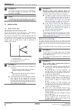
Page 18: ...loor heating loop T Room thermostat optional Provide adequate safeguards in the water circuit to be sure that the water pressure will never exceed the maximum allowable working pressure 4 bar Two shut off valves are delivered with the unit To facilitate service and maintenance install one at the water inlet and one at the water outlet of the indoor unit Mind position of the shut off valves Orienta...

Page 19: ...to guarantee full separation between domestic hot water and floor heating water circuit When using a 3 way valve or a 2 way valve in the water circuit the maximum change over time of the valve shall be less than 60 seconds Checking the water volume and expansion vessel pre pressure The unit is equipped with an expansion vessel of 10 litre which has a default pre pressure of 1 bar To assure proper ...

Page 20: ...er in and outlet 6 9 Charging water 1 Connect the water supply to a drain and fill valve see 5 2 Main components on page 11 2 Make sure the automatic air purge valve is open at least 2 turns 3 Fill with water until the manometer indicates a pressure of approximately 2 0 bar Remove air in the circuit as much as possible using the air purge valves Air present in the water circuit might cause malfunc...

Page 21: ...tic hot water thermistor S1L Flow switch S2S Benefit kWh rate power supply contact S3S Dual set point 2 contact S4S Dual set point 1 contact SS1 DIP switch TR1 Transformer 24 V for PCB V1S Spark suppression 1 V2S Spark suppression 2 X1M X9M Terminal blocks X6Y X9B Connector WARNING Electrical installation All field wiring and components must be installed by an installer and must comply with the ap...

Page 22: ...or tank with built in electrical booster heater EKHW T I M M B D 2 6 12 7 8 9 E A L 3 F K I C J H G 1 10 11 13 4 5 Item Description Required number of conductors Maximum running current 1 Power supply cable for outdoor unit 2 GND a a Refer to nameplate on outdoor unit 2 Indoor unit power supply and communication cable 3 GND b b Cable section 2 5 mm2 3 Power cable for bottom plate heater c c Bottom...

Page 23: ...ow 2 Connect the earth conductor yellow green to the earthing screw on the X1M terminal 3 Fix the cable with cable ties to the cable tie mountings to ensure strain relief Note only relevant field wiring is shown X3M X1M 1 2 3 1 3 2 1 2 3 CAUTION Use a dedicated power circuit for the backup heater and booster heater a Never use a power circuit shared by another appliance a Only applicable for tank ...

Page 24: ... requirements Power supply 230 V AC Maximum running current 100 mA Wiring the 2 way valve 1 Using the appropriate cable connect the valve control cable to the X2M terminal as shown on the wiring diagram 2 Fix the cable s with cable ties to the cable tie mountings to ensure strain relief Wiring the 3 way valve 1 Using the appropriate cable connect the valve control cable to the appropriate terminal...

Page 25: ...t kWh rate power supply is interrupted after elapse of time Type 3 This type of benefit kWh rate power supply is interrupted immediately Connect the indoor unit to a normal kWh rate power supply If the benefit kWh rate power supply is of type 2 or 3 power interruption of main power supply to outdoor unit the indoor unit should be connected to a normal kWh rate power supply to allow continuous indo...

Page 26: ...e configured by the installer to match the installation environment outdoor climate installed options etc and user expertise 8 1 DIP switch settings overview DIP switch SS2 is located on the switch box PCB see 5 3 Switch box main components on page 12 and allows configuration of domestic hot water tank installation room thermostat connection and pump operation Wire specification Value Type 2 wire ...

Page 27: ...mp when there is a simultaneous demand for more space heating cooling and domestic water heating a Only applicable in case DIP switch 2 ON Heating cooling priority Priority to highest demand side b b Heating cooling or domestic water heating mode can be restricted by schedule timer and or field settings 4 5 8 When no room thermostat is connected to the indoor unit toggle switch SS2 3 should be set...

Page 28: ...up heater type Refer to the wiring diagram 5 Booster heater circuit breaker F2B 2 Do not forget to turn on the booster heater circuit breaker F2B in the switch box applies only to units with optional domestic hot water tank 6 Earth wiring Make sure that the earth wires have been connected properly and that the earth terminals are tightened 7 Internal wiring Visually check the switch box on loose c...

Page 29: ...process the user interface cannot be operated 8 8 Setting the pump speed The pump speed can be selected on the pump see 5 2 Main components on page 11 The default setting is high speed III If the water flow in the system is too high e g noise of running water in the installation the speed can be set to medium speed II or low speed I The available external static pressure ESP expressed in kPa in fu...

Page 30: ...oint at low ambient temperature Lo_Ti the target outgoing water temperature when the outdoor temperature equals or drops below the low ambient temperature Lo_A Note that the Lo_Ti value should be higher than Hi_Ti as for low outdoor temperatures i e Lo_A warmer water is required 1 03 Set point at high ambient temperature Hi_Ti the target outgoing water temperature when the outdoor temperature equa...

Page 31: ... be configured by the installer according to the applicable legislation WARNING Be aware that the domestic hot water temperature at the hot water tap will be equal to the value selected in field setting 2 03 after a disinfection operation When the high domestic hot water temperature can be a potential risk for human injuries a mixing valve field supply shall be installed at the hot water outlet co...

Page 32: ...EKHTS The operation of the backup heater can altogether be enabled disabled or limited 4 00 Status defines whether backup heater operation is disabled 0 enabled 1 or limited 2 When 4 00 2 the backup heater is only allowed during domestic water heating mode NOTICE When the priority field setting is set to OFF 0 make sure that electrical power consumption does not exceed supply limits INFORMATION Ap...

Page 33: ...ill only be heated by the booster heater 5 02 Space heating priority status specifies whether space heating priority is enabled 1 or disabled 0 5 03 Space heating priority temperature outdoor temperature below which the domestic hot water will be heated by the booster heater only i e low outdoor temperature 5 04 Set point correction for domestic hot water temperature set point correction for the d...

Page 34: ...ump will be stopped by switching the 3 way valve The heat pump OFF temperature and the heat pump ON temperature and its relation with field settings 6 00 and 6 01 are explained in the illustration below 6 00 Start temperature difference determining the heat pump ON temperature THP ON See illustration 6 01 Stop temperature difference determining the heat pump OFF temperature THP OFF See illustratio...

Page 35: ...water to a temperature a few degrees above the set point temperature i e the booster heater OFF temperature These extra degrees are specified by the domestic hot water step length field setting Correct setting prevents the booster heater from repeatedly turning on and off i e chattering to maintain the domestic hot water set point temperature Note the booster heater will turn back on when the dome...

Page 36: ...is 2 C fixed below heat pump OFF temperature THP OFF INFORMATION There is no indication available which set point is active NOTICE The first set point heating cooling is the set point selected on the user interface In heating mode the first set point can be a fixed value or weather dependent In cooling mode the first set point can be a fixed value or weather dependent The second set point heating ...

Page 37: ...en the unit is configured to work with a room thermostat refer to 8 2 Room thermostat installation configuration on page 24 the maximum running timer will only be taken into account when there is a request for space heating or space cooling When there is no request for space heating or space cooling domestic water heating by the heat pump will continue until the heat pump OFF temperature see field...

Page 38: ...8 Leaving water setback value A Normal leaving water temperature set point or calculated weather depended set point B Calculated leaving water setback temperature set point t Time T Temperature In case the EKHW is installed and 4 03 4 or the EKHTS tank is installed it is advised to set the start time of automatic storage during night 6 04 on the moment that the setback function starts 9 06 Heating...

Page 39: ...ion is disabled the space heating by indoor unit is possible at all outdoor temperatures see operation ranges and permission signal for auxiliary boiler is always disactivated C 02 Bivalent operation status defines whether bivalent operation is enabled 1 or disabled 0 C 03 Bivalent ON temperature defines the outdoor temperature below which the permission signal for the auxiliary boiler will be act...

Page 40: ...mode 5 When parameter d 01 2 at the moment that the benefit kWh rate signal is sent by the electricity company that contact will close and the unit will go in forced off mode 6 1 When the unit is configured for restricted power supply condition mode see Appendix on page 51 INFORMATION When 4 07 Backup heater second step is disabled then the additional external backup heater signal will never be ac...

Page 41: ... permission F 01 Space cooling permission temperature defines the outdoor temperature below which space cooling is turned off Bottom plate heater control Applies only to installation with an outdoor unit ERLQ or in case the option bottom plate heater kit is installed F 02 Bottom plate heater ON temperature defines the outdoor temperature below which the bottom plate heater will be activated by ind...

Page 42: ...mestic hot water tank without electrical booster heater EKHTS 4 03 5 60 fixed 5 C 03 Set point only in combination with domestic hot water tank with built in electrical booster heater EKHW 4 03 5 70 55 80 5 C 04 Interval only in combination with domestic hot water tank without electrical booster heater EKHTS 4 03 5 60 40 60 5 min 04 Interval only in combination with domestic hot water tank with bu...

Page 43: ...storage start time 1 00 0 00 23 00 1 00 hour 05 Scheduled time reheat or continuous reheat 0 OFF 0 1 2 1 06 Scheduled time reheat start time 15 00 0 00 23 00 1 00 hour 07 Domestic hot water reheat set point 45 30 50 1 C 08 Domestic hot water reheat set point hysteresis 10 2 20 1 C 7 DT for booster heater and dual set point control 00 Domestic hot water step length only in combination with domestic...

Page 44: ...ditional external backup heater temperature 0 25 25 1 C 04 Bivalent hysteresis or additional external backup heater hysteresis 3 2 10 1 C 05 Not applicable d Benefit kWh rate power supply local shift value weather dependent 00 Switching off heaters 0 0 1 2 3 1 01 Unit connection to benefit kWh rate power supply 0 OFF 0 1 2 1 02 Not applicable Do not change the default value 0 OFF 03 Local shift va...

Page 45: ...ion number selection 1 1 20 1 06 Heating set point of selected action number F 05 25 0 c 15 55 1 C 07 Time of selected action number F 05 0 c 0 72 12 hour 08 Underfloor heating screed dry out program enabled disabled 0 OFF 0 1 1 09 Latest action number executed 0 0 21 Read only 0 a The storage and reheat function is only applicable in case 4 03 4 or 5 b Only possible to modify the first 3 minutes ...

Page 46: ...tes or when reaching the set temperature The test run operation can be stopped manually by pressing the z button once If there are misconnections or malfunctions an error code will be displayed on the user interface Otherwise the user interface will return to normal operation 4 To resolve the error codes see 11 3 Error codes on page 48 9 3 Underfloor heating screed dry out program This function al...

Page 47: ...y out program as follows 1 Set in F 08 Underfloor heating screed dry out program enabled disabled to 1 enabled 2 When finished press the z button to exit the FIELD SET MODE 2 Activate 1 Push the z button 4 times so the t icon will be displayed 2 To start the Underfloor heating dry out program press the y button 3 The Underfloor heating dry out program will start and display the action and temperat...

Page 48: ...5M applications with domestic hot water tank only and K4M by use of an ohmmeter All contacts of these contactors must be in open position DANGER ELECTRIC SHOCK Before carrying out any maintenance or repair activity always switch off the circuit breaker on the supply panel remove the fuses or open the protection devices of the unit Make sure that before starting any maintenance or repair activity a...

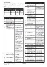
Page 49: ... and immediately after operation See 2 General safety precautions on page 2 INFORMATION For problems related to the optional solar kit for domestic water heating refer to the troubleshooting in the installation manual of that kit POSSIBLE CAUSES CORRECTIVE ACTION The temperature setting is not correct Check the controller set point The water flow is too low Check that all shut off valves of the wa...

Page 50: ...ckup heater operation status field setting 4 00 is turned on see 8 9 Field settings on page 26 Check whether or not the thermal protector of the backup heater has been activated refer to Main components 18 Backup heater thermal protector on page 11 for location of the reset button Check if booster heater and backup heater are configured to operate simultaneously field setting 4 01 see 8 9 Field se...

Page 51: ...asured by R3T Contact your local dealer AA Backup heater thermal protector is open Reset the thermal protector by pressing the reset button refer to 5 2 Main components on page 11 for location of the reset button Check the reset button of the thermal protector If both the thermal protector and the controller are reset but the AA error code persists the backup heater thermal fuse has blown Contact ...

Page 52: ...ure The error can only be reset in the test mode as follows First press the z button 4 times so the t icon will be displayed Then press the y button 1 time Finally push the z button to exit the test mode Notes In this case F 09 Latest action number executed will contain the latest action number executed F 08 Underfloor heating screed dry out program enabled 1 disabled 0 is always cleared to 0 disa...

Page 53: ... refrigerant gas side Ø15 9 mm 5 8 inch Ø15 9 mm 5 8 inch Expansion vessel volume 10 l 10 l maximum working pressure MWP 3 bar 3 bar Pump type water cooled water cooled no of speed 3 3 Sound pressure level Refer to technical data Refer to technical data Internal water volume 5 5 l 5 5 l Pressure relief valve water circuit 3 bar 3 bar Operation range water side heating 15 50 C 15 50 C cooling 5 22 ...

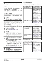
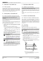
Page 54: ...backup heater operation occurs because of User request to heat up water to the space heating loops The temperature of this water is too low and is out of the operation range during initial start up for example Refer to 8 5 Initial start up at low outdoor ambient temperatures on page 25 and 8 5 Re start at low outdoor ambient temperatures on page 53 During heating operation the water temperature be...

Page 55: ...coil or the electrical booster heater 3 or backup heater 4 When the domestic hot water temperature is below the user configured set point the 3 way valve will be activated to heat the domestic hot water by means of the heat pump In case of high domestic hot water temperature setting the booster heater 11 5 or backup heater 4 6 provides heating 1 For tank without electrical booster heater EKHTS the...

Page 56: ...ns with restricted power supply condition mode it is not recommended to connect the system to a benefit kWh rate power supply All items related to benefit kWh rate power supply should be neglected 8 START UP AND CONFIGURATION 8 5 Re start at low outdoor ambient temperatures When re starting at low ambient temperature it is important to ensure that the unit operates within its operation range as so...

Page 57: ...le for installations with restricted power supply condition mode 6 DT for heat pump domestic water heating mode scheduled storage and reheat domestic water heating 6 03 6 08 are not applicable for installations with restricted power supply condition mode WARNING Be aware that the domestic hot water temperature at the hot water tap will be equal to the value selected in field setting 2 03 after a d...

Page 58: ...dition mode d 02 shall be set to 1 to activate the total restricted power consumption Do not change this value Local shift value weather dependent The local shift value weather dependent field setting is only relevant in case weather dependent set point see field setting 1 Weather dependent set point on page 27 is selected d 03 Local shift value weather dependent determines the shift value of the ...

Page 59: ...ble disable 0 OFF 0 1 06 Low ambient temperature Lo2_A 20 10 25 1 C 07 High ambient temperature Hi2_A 35 25 43 1 C 08 Set point at low ambient temperature Lo2_Ti 22 5 22 1 C 09 Set point at high ambient temperature Hi2_Ti 18 5 22 1 C 2 Disinfection function 00 Operation interval Fri Mon Sun All 01 Status 1 ON 0 1 02 Start time 23 00 0 00 23 00 1 00 hour 03 Set point 70 55 80 5 C 04 Interval 10 5 6...

Page 60: ...5 95 5 min 02 Anti recycling time 3 0 10 0 5 hour 03 Not applicable 04 Additional running time at 4 02 F 01 95 0 95 5 min 9 Heating and cooling set point ranges 00 Heating set point upper limit 55 37 55 1 C 01 Heating set point lower limit 25 15 37 1 C 02 Cooling set point upper limit 22 18 22 1 C 03 Cooling set point lower limit 5 5 18 1 C 04 Overshoot setting b 1 1 4 1 C Automatic set back funct...

Page 61: ...ad only 01 EEPROM version Read only 02 Unit model identification Do not change the default value depending on model 03 Liquid refrigerant temperature Read only 1 C 04 Inlet water temperature Read only 1 C F Option setup 00 Pump operation stop 0 enabled 0 1 1 01 Space cooling permission temperature 20 10 35 1 C 02 Bottom plate heater ON temperature 3 3 10 1 C 03 Bottom plate heater hysteresis 5 2 5...

Page 62: ......

Page 63: ......

Page 64: ...4PW62570 1A 01 2011 Copyright 2010 Daikin ...

Reviews: