Installation manual
19
EKHBH/X008BB
Indoor unit for air to water heat pump system
4PW62570-1A – 01.2011
7.3.
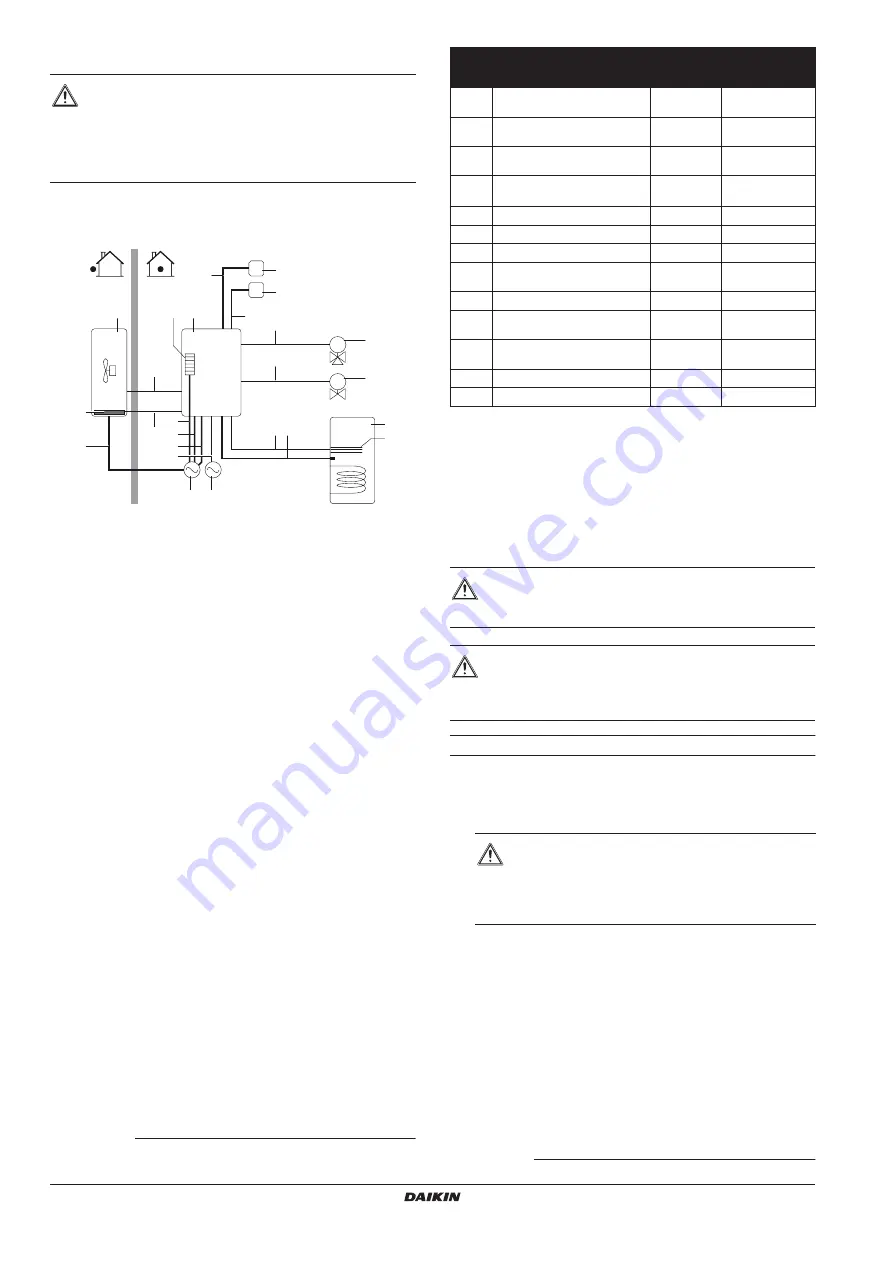
System overview of field wiring
The illustration below gives an overview of the required field wiring
between several parts of the installation. Refer also to
application examples" on page 5
A
Single power supply for outdoor unit, backup heater and
booster heater
B
Outdoor unit
C
Bottom plate heater
D
Backup heater
(1)
E
Indoor unit
F
Room thermostat (optional)
G
3-way valve for domestic hot water tank (optional)
H
2-way valve for cooling mode (field supply)
I
Domestic hot water tank (optional)
J
Booster heater
(2)
K
User interface (digital controller)
L
Power supply (normal kWh rate power supply: only in case
of benefit kWh rate power supply installation)
Field wiring guidelines
■
Most field wiring on the indoor unit side is to be made on the
terminal block inside the switch box. To gain access to the
terminal block, remove the indoor unit cover and switch box
service panel, see
"5.1. Opening the indoor unit" on page 10
■
Cable tie mountings are provided at the bottom of the switch
box. Fix all cables using cable ties (field supply).
■
A dedicated power circuit is required for the backup heater.
■
Installations equipped with a domestic hot water tank (optional),
require a dedicated power circuit for the
booster heater
(3)
.
Please refer to the domestic hot water tank installation manual.
WARNING
■
Switch off the power supply before making any
connections.
■
All field wiring and components must be installed by a
licensed electrician and must comply with the
applicable legislation.
(1) For tank without electrical booster heater (EKHTS), the backup heater will
be used in domestic water heating mode.
(2) Only applicable for tank with built-in electrical booster heater (EKHW*).
T
I
M
M
B
D
2
6
12
7
8 9
E
A
L
3
F
K
I
C
J
H
G
1
10
11
13
4
5
Item
Description
Required
number of
conductors
Maximum
running current
1
Power supply cable for outdoor
unit
2+GND
(a)
(a) Refer to nameplate on outdoor unit.
2
Indoor unit power supply and
communication cable
3+GND
(b)
(b) Cable section 2.5 mm
2
3
Power cable for bottom plate
heater
(c)
(c) Bottom plate heater cable is only applicable in combination with ERLQ or
in case of optional EKBPHT kit.
2
(d)
(d) Minimum cable section 0.75 mm
2
4
Power supply cable for backup
heater
2+GND or
3+GND
(e)
(e) See table under
"Connection of the backup heater power supply" on page 20
5
Room thermostat cable
3 or 4
100 mA
6
3-way valve control cable
2+GND
100 mA
7
2-way valve control cable
2+GND
100 mA
8
Booster heater power supply
and thermal protection cable
(f)
(f)
Only applicable for tank with built-in electrical booster heater (EKHW*).
4+GND
9
Thermistor cable
2
(g)
(g) The thermistor and connection wire (12 m) are delivered with the domestic hot
water tank.
10
Booster heater power supply
cable
2+GND
13 A
11
Benefit kWh rate power supply
cable (voltage free contact)
2
(h)
(h) Cable section 0.75 mm
2
till 1.25 mm
2
, maximum length: 50 m.
Voltage free contact shall ensure the minimum applicable load of 15 V DC,
10 mA.
12
User interface cable
2
(i)
(i)
Cable section 0.75 mm
2
till 1.25 mm
2
, maximum length: 500 m.
13
Normal kWh rate power supply
2+GND
CAUTION
Select all cables and wire sizes in accordance with the
applicable legislation.
WARNING
After finishing the electric work, confirm that each electric
part and terminal inside the electric parts box is connected
securely.
WARNING
Switch off all power supply – i.e. outdoor unit power
supply and backup heater and domestic hot water
tank power supply (if applicable) – before removing
the switch box service panel.
(3) Only applicable for tank with built-in electrical booster heater (EKHW*).


