7 Installation
Installation manual
10
EKHWS150~300D3V3
Domestic hot water tank with option kit for air to water heat pump
system
4P510672-1C – 2023.02
INFORMATION
The jumper is factory‑set to apply for installation in
accordance with configurations E1 and E2.
5
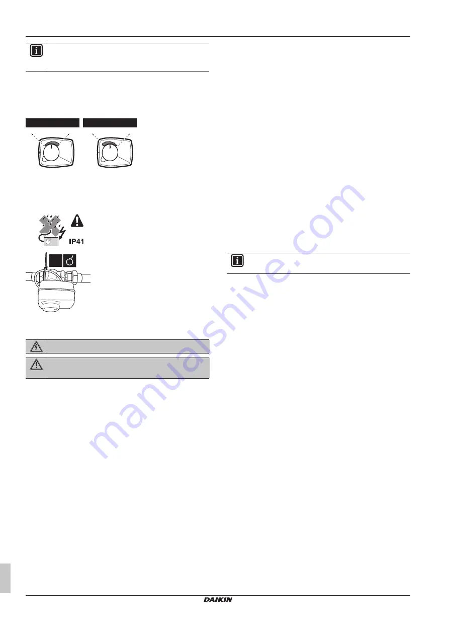
Put the knob on the motor in a 12 o'clock position and push the
motor on the sleeve. Do NOT rotate the sleeve during this
action, so as to maintain the valve position as set during step 4.
6
Put the scale on the valve according to the applicable
configuration.
a
a
b
b
E1+E2
E3+E4
a
DHW tank
b
Room heating
7
To provide stress relief, fix the power supply cable to the 3‑way
valve body with a cable tie (field supply). Fix it so that possible
condensate cannot enter the 3‑way valve motor via the cable.
1×
7.5
Connecting the electrical wiring
DANGER: RISK OF ELECTROCUTION
WARNING
ALWAYS use multicore cable for power supply cables.
7.5.1
About connecting the electrical wiring
Before connecting the electrical wiring
Make sure the water piping is connected.
Typical workflow
Connecting the electrical wiring typically consists of the following
stages:
1
Connecting the electrical wiring on the indoor unit (or control
box).
2
Connecting the electrical wiring on the domestic hot water tank.
7.5.2
To connect the electrical wiring to the
indoor unit
For EHBH/X only:
1
Install the booster heater power supply sticker in the unit switch
box on the location shown in the illustration below.
2
Mount the contactor K3M and terminal block X7M. Fix the
contactor with the 2 contactor fixing screws supplied. Fix the
terminal block with the 2 tapping screws supplied.
3
Install the jumper wire from the accessory bag in between
terminals X2M/10 and X2M/11a (see illustration below).
4
Route the booster heater power supply cable (coming from
K3M) and the thermistor cable through the switch box board as
shown in the illustration below.
5
Connect the earth wire of the booster heater power supply
cable to the switch box earthing screw (located next to the
contactor K3M).
6
Connect the N and L wires of the booster heater power supply
cable to the lower contactor terminals of K3M.
7
Connect the upper terminals of X7M/1 and X7M/2 to the upper
contactor terminals of K3M.
8
Plug the connector of the contactor K3M in socket X13A (RED)
of the main PCB.
9
Plug the thermistor cable connector in socket X9A of the PCB.
10
Connect the earth wire of the terminal block X7M to the switch
box earthing screw (located above the terminal).
11
Connect the booster heater power supply cable (field supply) to
the contactor terminals X7M/1+2+earth.
12
Connect the 3-way valve cable to terminals X2M/12, X2M/13
and X2M/14a.
13
Fix the cables to the cable tie mountings with cable ties to
ensure strain relief.
14
When routing out cables, make sure that these do not obstruct
mounting of the unit cover.
INFORMATION
Only the relevant field wiring is shown.


