7 Installation
Installation manual
11
EKHWS150~300D3V3
Domestic hot water tank with option kit for air to water heat pump
system
4P510672-1C – 2023.02
X5M
K3M
X2M
X1M
X9A
X13A
X7M
12
14a
L N PE
10 11a
R5T
>50 mm
M3S
L
BRN
BLU
BLK
N Y
N
X7M
L
13
F2B
230 V AC
3 kW
L N
N
X8M
L
2
K3M
1
X2M
14a 13 12
2
1
M3S
L
BLK
BLU
BRN
N Y
10
11a
X2M
X1M
X5M
c
b
a
b+c+d
d
a
a
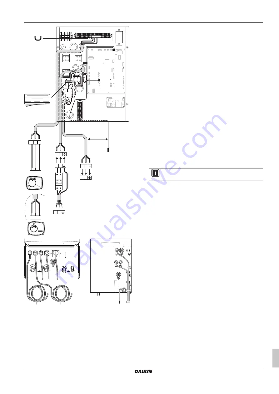
Thermistor cable
b
Booster heater power supply cable
c
3-way valve cable
d
Booster heater cable
7.5.3
To connect the electrical wiring to the
outdoor unit
For EBLQ/EDLQ only:
1
Install the booster heater power supply sticker in the unit switch
box on the location shown in the illustration below.
2
Mount the contactor K3M and terminal block X4M. Fix the
contactor with the 2 contactor fixing screws supplied. Fix the
terminal block with the 2 tapping screws supplied.
3
Install the jumper wire from the accessory bag in between
terminals X2M/7 and X2M/8.
4
Connect the earth wire of the booster heater power supply
cable to the switch box earthing screw.
5
Connect the N and L wires of the booster heater power supply
cable to the lower contactor terminals of K3M.
6
Connect the upper terminals of X4M/1 and X4M/2 to the upper
contactor terminals of K3M.
7
Connect the signal wires of contactor K3M (discard the
connector) to control box terminals X8M/1 and X8M/2.
8
Connect the wires of the thermistor cable to the control box
terminals X2M/3 and X8M/4.
9
Connect the earth wire of the control box terminal X4M to the
switch box earthing screw (located above the terminal).
10
Connect the booster heater cable (field supply) to the control
box terminals X4M/1+2+earth.
11
Connect the 3-way valve cable to control box terminals X8M/3,
X8M/4 and X8M/5.
12
Fix the cables to the cable tie mountings with cable ties to
ensure strain relief.
13
When routing out cables, make sure that these do not obstruct
mounting of the unit cover.
INFORMATION
Only the relevant field wiring is shown.


