background image

Installation manual

15

EMRQ8~16ABY1

Daikin Altherma outdoor unit

4P501819-1 – 2017.08

5

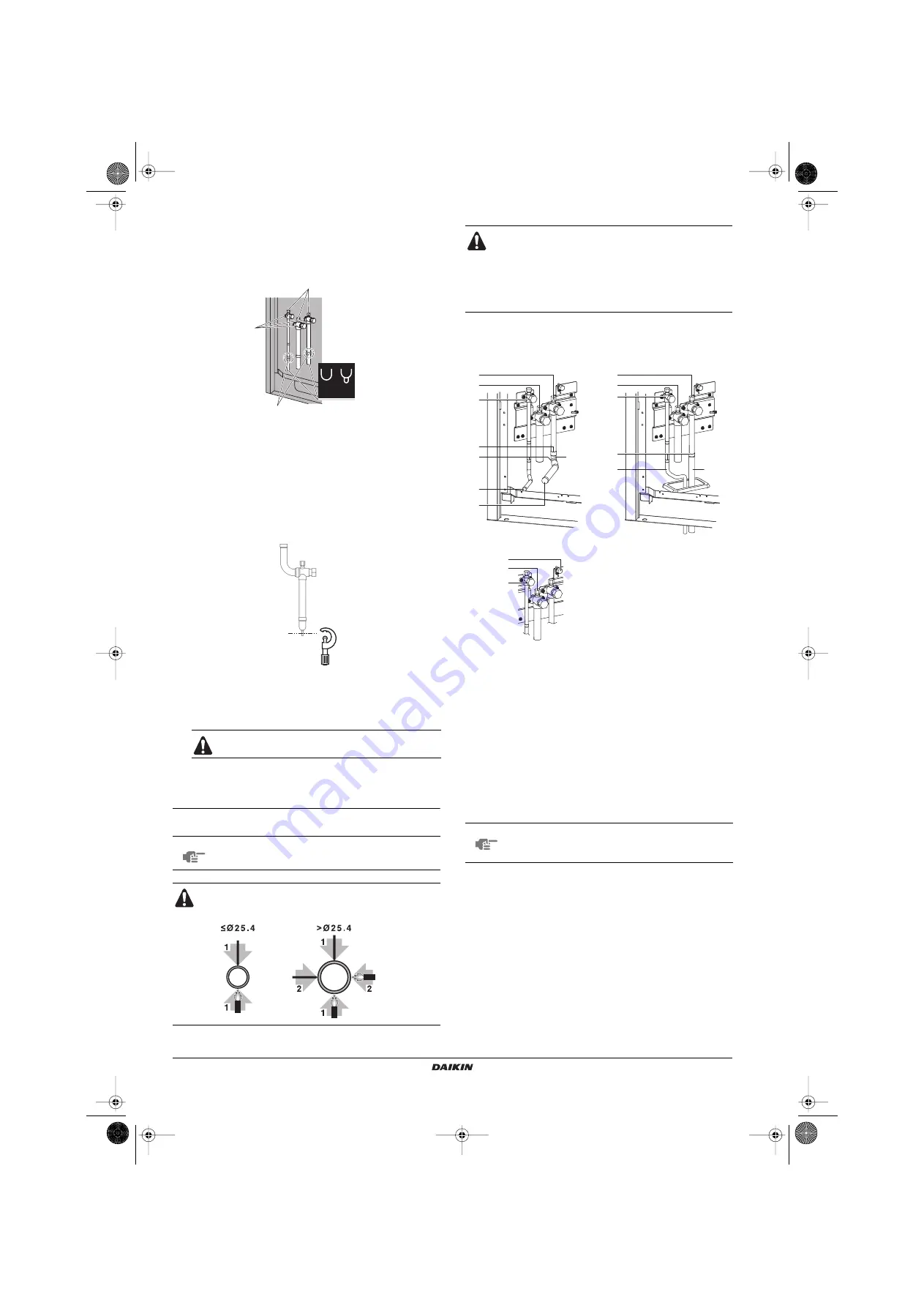
In case the pinched piping lower part looks like detail A in the
figure below, follow instructions as per procedure steps 

7

-

8

.

In case the pinched piping lower part looks like detail B in the
figure below, follow instructions as per procedure steps 

6

-

7

-

8

.

6

For the discharge gas stop valve, cut off the lower part of the
smaller pinched piping with an appropriate tool (e.g. pipe cutter,
a pair of nippers, …). Let the remaining oil drip out in case the
recovery was not complete:

Wait until all oil is dripped out.

7

Cut the pinched piping of the liquid pipe and discharge gas pipe
stop valve off with a pipe cutter just above the brazing point or
marking if there is no brazing point.

8

Wait until all oil is dripped out before continuing with the
connection of the field piping in case the recovery was not
complete.

3.

Connecting refrigerant piping to the outdoor unit.

Connection from the stop valves to the field piping using accessory
pipes should be as below:

The connections above to the branch kits, are the responsibility of the
installer (field piping).

1

Pinched piping

2

Stop valve

3

Service port

4

Point of melting the brazing metal; cut pipe off just above this 
brazing or marking point

Never remove the pinched piping by brazing.

NOTE

All local interunit piping are field supplied except
the accessory pipes.

Precautions when connecting field piping.

Add brazing material as shown in the figure.

B

A

3

2

4

1

Be sure to use the supplied accessory pipes when
carrying out piping work in the field.

Be sure that the field installed piping does not touch
other pipes, the bottom panel or side panel. Especially
for the bottom and side connection, be sure to protect
the piping with suitable insulation, to prevent it from
coming into contact with the casing.

A

Front connection

B

Bottom connection

C

EMRQ8

1

Liquid pipe stop valve

2

Suction gas pipe stop valve (not used)

3

Discharge gas pipe stop valve

4

Brazing

5

Liquid accessory pipe (1)

6

Discharge gas accessory pipe (1)

7

Accessory joint (angle 90°) (2)

8

Liquid accessory pipe (2)

9

Discharge gas accessory pipe (2)

NOTE

Make sure that the onsite piping does not come in
contact with other piping, the bottom frame or side
panels of the unit.

A

B

C

1

2

7

4
4

3

1

2

2

3

6

5

4

8

9

1

3

4PEN501819-1.book  Page 15  Wednesday, September 13, 2017  12:52 PM

Summary of Contents for EMRQ8ABY1

Page 1: ...INSTALLATION MANUAL EMRQ8ABY1 EMRQ10ABY1 EMRQ12ABY1 EMRQ14ABY1 EMRQ16ABY1 Daikin Altherma outdoor unit 4PEN501819 1 book Page 1 Wednesday September 13 2017 12 52 PM...

Page 2: ...vlastn zodpovednos e zariadenie na ktor sa vz ahuje toto vyhl senie 25 w tamamen kendi sorumlulu unda olmak zere bu bildirinin ilgili oldu u donan m n n a a daki gibi oldu unu beyan eder 01 as set ou...

Page 3: ...aksim l pie aujam temperat ra TS TSmin Minim l temperat ra zem spiediena pus L C TSmax Pies tin t temperat ra saska ar maksim lo pie aujamo spiedienu PS M C Dzesin t js N Spiediena dro bas ier ces ies...

Page 4: ...uming after electrical installation is done on any indoor or outdoor unit 17 General guidelines 16 Set up 17 Leak test 18 Vacuum drying 18 11 Pipe insulation 18 12 Electrical wiring work 19 12 1 Preca...

Page 5: ...on Improper installation or attachment of equipment or accessories could result in electric shock short circuit leaks fire or other damage to the equipment Be sure only to use accessories and optional...

Page 6: ...ing accessories are supplied with the unit 1 EKHBRD connection is possible for EKHBRD_ABX and EKHBRD_AC Connection is NOT possible for EKHBRD_AA or EKHBRD_AB models For more details see technical data...

Page 7: ...ectrical component box cover as follows For service purposes the push buttons on the switch box PCB need to be accessed To access these push buttons the electrical component box cover does not need to...

Page 8: ...16 9 Electronic expansion valve subcooling Y2E Y5E 3 Heat exchanger 10 Electronic expansion valve charge Y4E 4 Fan 11 4 way valve heat exchanger Y2S Y9S 5 Fan motor M1F M2F 12 4 way valve pipe Y8S 6...

Page 9: ...field wiring with cable ties to the switch box to ensure strain relief 4 Magnetic contactor K2M 5 Current sensor PCB 2 1 4 5 2 3 3 3 3 3 3 3 3 1 1 Main PCB 2 Sub 1 PCB 3 Terminal block X1M Main termi...

Page 10: ...to leak Locations where a mineral oil mist spray or vapour may be present in the atmosphere Plastic parts may deteriorate and fall off or cause water leakage Locations where equipment that produces el...

Page 11: ...and snow install a baffle plate on the air side of the outdoor unit In heavy snowfall areas it is very important to select an installation site where the snow will not affect the unit If lateral snow...

Page 12: ...nit take into account the following 1 Fragile handle the unit with care Keep the unit upright in order to avoid compressor damage 2 Choose on beforehand the path along which the unit is to be brought...

Page 13: ...m above the foundation surface CAUTION To avoid injury do not touch the air inlet or aluminium fins of the unit WARNING Tear apart and throw away plastic packaging bags so that children will not play...

Page 14: ...case the required pipe sizes inch sizes are not available it is also allowed to use other diameters mm sizes taken the following into account select the pipe size nearest to the required size use the...

Page 15: ...net header to indoor unit 40 m Example 1 unit 5 b c d e 40 m Example 2 unit 3 b e 40 m unit 5 f h 40 m Example 3 unit 5 f 40 m Maximum allowable height difference Difference in height between outdoor...

Page 16: ...An oxidized film adversely affects valves and compressors in the refrigerating system and prevents proper operation The nitrogen pressure should be set to 0 02 MPa i e just enough so it can be felt o...

Page 17: ...event rusting When passing electrical wiring through the knock out holes wrap the wiring with protective tape to prevent damage as shown above 3x 1 2 3 NOTE Any gas or oil remaining inside the stop va...

Page 18: ...are the responsibility of the installer field piping 1 Pinched piping 2 Stop valve 3 Service port 4 Point of melting the brazing metal cut pipe off just above this brazing or marking point Never remov...

Page 19: ...valve After handling the service port make sure to tighten the service port cover securely For the tightening torque refer to the table below Check for refrigerant leaks after tightening the service...

Page 20: ...being present in the refrigerant piping for example rainwater may have entered the piping first carry out the vacuum drying procedure below until all moisture has been removed and consider the install...

Page 21: ...branch kits entirely Be sure to insulate liquid and discharge piping for all units Use heat resistant polyethylene foam which can withstand a temperature of 70 C for liquid piping and polyethylene fo...

Page 22: ...t operation If there exists the possibility of reversed phase after a momentary black out and the power goes on and off while the product is operating attach a reversed phase protection circuit locall...

Page 23: ...tem overview of field wiring Field wiring consists out of power supply always including earth and indoor outdoor communication transmission wiring 12 4 Requirements The power supply must be protected...

Page 24: ...sion wiring Care should be taken for connecting the wires to the terminal block 1 Power supply inside a conduit 2 Conduit 3 Power supply 4 Cut off the shaded zones before usage 5 Through hole cover 1...

Page 25: ...en connecting the power supply the earth connection must be made before the current carrying connections are established When disconnecting the power supply the current carrying connections must be se...

Page 26: ...nhouse gases label peal off the applicable language and stick it on top of 1 2 Factory refrigerant charge see unit name plate 3 Additional refrigerant amount charged 4 Total refrigerant charge 5 Green...

Page 27: ...further explanation on how to do the necessary settings 6 Push the BS1 MODE button for 5 sec the H1P LED is on w 7 Push the BS2 SET button 20 times until following LED combination is reached 8 Push th...

Page 28: ...liquid and discharge side The suction stop valve should remain closed at all times 10 Damaged equipment Check the inside of the unit on damaged components or squeezed pipes 11 Refrigerant leak Check...

Page 29: ...shing the BS3 RETURN button defines the setting Finally when pushing the BS3 RETURN button again the operation starts according to the setting Pushing BS1 MODE button will get you back to the initial...

Page 30: ...ralized control will display on the remote controller It may take 10 minutes to bring the state of the refrigerant uniform before the compressor starts During the test operation the refrigerant runnin...

Page 31: ...ge has been finished correctly Recalculate the required amount of refrigerant from the piping length and add an adequate amount of refrigerant In case the test operation was interrupted or the unit wa...

Page 32: ...7 1 Introduction The installer and system specialist shall secure safety against leakage according to local regulations or standards The following standards may be applicable if local regulations are...

Page 33: ...t of the refrigerant of oil and of other parts must be done in accordance with relevant local and national legislation 19 UNIT SPECIFICATIONS Technical specifications Electrical specifications amount...

Page 34: ...4PEN501819 1 book Page 1 Wednesday September 13 2017 12 52 PM...

Page 35: ...4PEN501819 1 book Page 2 Wednesday September 13 2017 12 52 PM...

Page 36: ...4P501819 1 2017 08 Copyright 2017 Daikin 4P501819 1 0000000M 4PEN501819 1 book Page 1 Wednesday September 13 2017 12 52 PM...

Reviews: