D
–EIMAC00708-16EN - 40/76
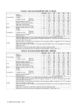
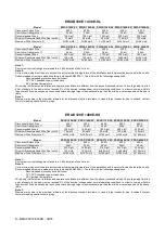
ERAD 120E ÷460E-SL
Model
ERAD 120E-SL ERAD 140E-SL ERAD 160E-SL ERAD 190E-SL ERAD 210E-SL
Disconnect Switch Size
400 A
400 A
400 A
400 A
400 A
Short circuit rating (note 1)
25 kA
25 kA
25 kA
25 kA
25 kA
Recommended Fuses
125 A gG
160 A gG
160 A gG
200 A gG
200 A gG
Minimum Recommended Wire Size (note 2)
70 mm2
95 mm2
95 mm2
120 mm2
120 mm2
Maximum Wire Size (note 3)
2x185 mm2
2x185 mm2
2x185 mm2
2x185 mm2
2x185 mm2
Model
ERAD 240E-SL ERAD 300E-SL ERAD 350E-SL ERAD 410E-SL ERAD 460E-SL
Disconnect Switch Size
400 A
400 A
400 A
400 A
400 A
Short circuit rating (note 1)
25 kA
25 kA
25 kA
25 kA
25 kA
Recommended Fuses
200 A gG
250 A gG
315 A gG
355 A gG
355 A gG
Minimum Recommended Wire Size (note 2)
120 mm2
150 mm2
2x95 mm2
2x95 mm2
2x120 mm2
Maximum Wire Size (note 3)
2x185 mm2
2x185 mm2
2x185 mm2
2x185 mm2
2x185 mm2
Note 1:
Short-circuit current ratings are referred to a 0.25 s duration of short circuit.
Note 2:
Correct wire sizing must take into account the actual ambient temperature of the installation and the protection device installed on-site.
Recommended wire size is made according to standard EN60204-1
– Table 6.E with the following assumptions:
-
Recommended protection devices (fuses)
-
70°C PVC stranded copper conductors
-
40°C ambient temperature
Wire sizing is different as installation and operation conditions are different from the above mentioned values. The voltage drop from the
point of supply to the load must not exceed 5% of the nominal voltage under normal operating conditions. In order to comply with this
requirement, it can be necessary to use conductors having a larger cross-sectional area than the minimum value reported on the above
table.
Note 3:
Maximum wire size is the maximum allowed by the disconnect switch terminals. In case a larger conductor size is needed, contact
factory for asking special incoming lugs.
Connect electrical power supply cables to the terminals of the main disconnect switch located on th
e machine’s terminal
board. The access panel must have a hole of appropriate diameter for the cable used and its cable gland. A flexible duct
can also be used, containing the three power phases plus earth.
In any case, absolute protection against any water penetrating through the connection point must be ensured.
Control Circuit Wiring
The control circuit on the unit is designed for 115V supply. Control power is supplied from a factory-wired transformer
located in the electrical panel. No additional wiring is thus required.
However, a customer terminal board is available for field input/output connections (see Figure 18) to allow a remote
control of the unit.
Electrical heaters
EW AD E-SS/SL units have an electrical anti-freeze heater that is installed directly in the evaporator. Each circuit also has
an electrical heater installed in the compressor, whose purpose is to keep the oil warm and avoid the transmigration of
refrigerant within. Obviously, the operation of the electrical heaters is guaranteed only if there is a constant power supply.
If it is not possible to keep the machine on when inactive during winter, apply at least two of the procedures described in
the “Installation – Mechanical” section under the “Evaporator and recuperative exchangers antifreeze protection”
paragraph.
In case a separate accumulation tank (optional) is requested, its electrical anti -freeze heater must have a separate power
supply.
Electrical power supply to the pumps
On request, a kit can be installed in EWAD E-SS/SL units for fully-cabled and microprocessor-controlled pumping. No
additional control is required in this case.

