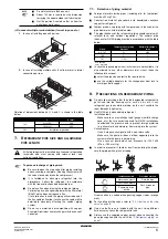
ERQ100~140A7V1B
Inverter condensing unit
4PW51321-1
Installation manual
10
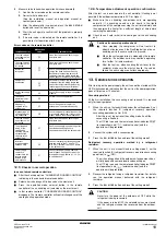
See
To avoid compressor breakdown. Do not charge the refrigerant
more than the specified amount.
■
This outdoor unit is factory charged with refrigerant and
depending on pipe sizes and pipe lengths some systems require
additional charging of refrigerant. See
additional refrigerant to be charged" on page 10
■
In case re-charge is required, refer to the nameplate of the unit.
The nameplate states the type of refrigerant and necessary
amount.
Installation limitations
How to calculate the additional refrigerant to be charged
Additional refrigerant to be charged R (kg)
R should be rounded off in units of 0.1 kg
R=(Total length (m) of liquid piping size at Ø9.5)x0.054
Determine the weight of refrigerant to be charged additionally
referring to the item "Additional refrigerant charge" in
calculate the additional refrigerant to be charged" on page 10
and fill
in the amount in the "Additional refrigerant charge label" attached to
the unit.
Precautions when adding R410A
Be sure to charge the specified amount of refrigerant in liquid state to
the liquid pipe.
Since this refrigerant is a mixed refrigerant, adding it in gas form may
cause the refrigerant composition to change, preventing normal
operation.
■
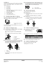
Before charging, check whether the refrigerant cylinder is
equipped with a siphon tube or not.
10.1. Important information regarding the refrigerant
used
This product contains fluorinated greenhouse gases covered by the
Kyoto Protocol. Do not vent gases into the atmosphere.
Refrigerant type:
R410A
GWP
(1)
value:
1975
(1)
GWP = global warming potential
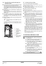
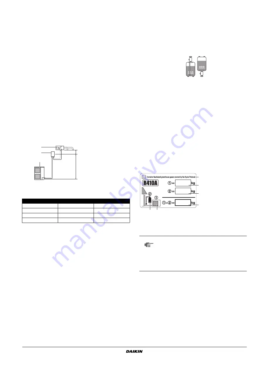
Please fill in with indelible ink,
■
➀
the factory refrigerant charge of the product,
■
➁
the additional refrigerant amount charged in the field and
■
➀
+
➁
the total refrigerant charge
on the fluorinated greenhouse gases label supplied with the product.
The filled out label must be adhered on the inside of the product and
in the proximity of the product charging port (e.g. on the inside of the
service cover).
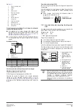
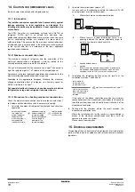
1
Pressure reducing valve
2
Nitrogen
3
Tank
4
Siphon system
5
Measuring instrument
6
Vacuum pomp
7
Valve A
8
Gas line stop valve
9
Outdoor unit
10
Liquid line stop valve
11
Air handling unit
12
Stop valve service port
13
Charge hose
1
Outdoor unit
2
Valve kit
3
Air handling unit
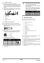
Max (m)
Min (m)
L1
50
5
L2
5
—
A
–5 / +5
(*)
(*)
Below or above the outdoor unit.
—
B
–35 / +35
(*)
—
L1
L2
A
B
1
2
3
Charge the liquid
refrigerant with the cylinder
in upright position.
Charge the liquid
refrigerant with the cylinder
in up-side-down position.
NOTE
National implementation of EU regulation on certain
fluorinated greenhouse gases may require to provide
the appropriate official national language on the unit.
Therefore, an additional multilingual fluorinated
greenhouse gases label is supplied with the unit.
Sticking instructions are illustrated on the backside of
that label.
3
5
6
2
1
4
1
factory refrigerant charge
of the product:
see unit name plate
2
additional refrigerant
amount charged in the
field
3
total refrigerant charge
4
Contains fluorinated
greenhouse gases
covered by the Kyoto
Protocol
5
outdoor unit
6
refrigerant cylinder and
manifold for charging

