Installation manual
17
ERQ100~140A7V1B
Inverter condensing unit
4PW51321-1
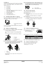
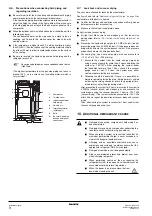
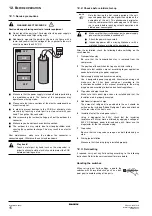
3.3 Possible settings for function D and E
For function D (
) only: the noise of level
3<
level 2< level 1 (
).
For function E (
) only: the power consumption of
level 1< level 2 < level 3 (
).
4
Push the
button and the setting is defined.
5
When the
button is pushed again, the operation
starts according to the setting.
Refer to the service manual for more details and for other settings.
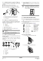
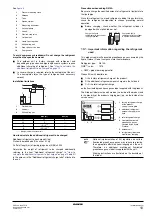
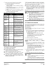
Confirmation of the set mode
The following items can be confirmed by setting mode 1 (H1P
led is off)
Check the led indication in the field marked
.
1
Indication of the present operation state
2
Indication of COOL/HEAT selection setting
3
Indication of low noise operation state
4
Indication of power consumption limitation setting
12.4. Test operation
■
Check the stop valves
Make sure to open the gas and liquid line stop valves.
■
After installation, perform the test operation.
Unless the test operation is performed, the error code "
U3
" is
shown on the remote controller and the unit cannot be operated.
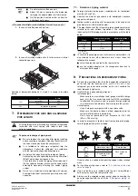
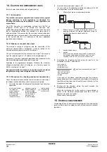
Performing the test operation
1
To protect the compressor, make sure to turn on the power
supply 6 hours before starting operation.
2
Set to setting mode 1 (H1P led is off) (refer to
3
Press the
button for 5 seconds when the unit is at a
standstill. The test operation starts when the H2P led blinks and
the remote controller indicates
(test operation) and
(external control).
It may take 10 minutes to bring the state of refrigerant uniform
before the compressor starts, but that is not a malfunction.
The test operation is automatically carried out in cooling mode
during 15~30 minutes.
Depending on the situation, the refrigerant running sound or the
sound of a magnetic solenoid valve may rise during this
operation.
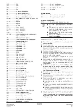
The following items are automatically checked:
-
Check for incorrect wiring
-
Check if stop valves are open
-
Check of refrigerant charge
-
Automatic judgement of piping length
4
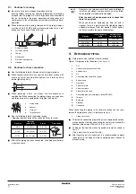
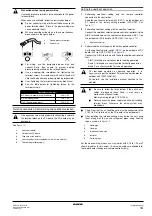
After the test operation (maximum 30 minutes), the unit
automatically stops. Check the operation results by the outdoor
unit led indication.
H1P
H2P
H3P
H4P
H5P
H6P
H7P
w x
x
x
x
x c
(*)
(*)
This setting = factory setting.
w x
x
x
x c x
w x
x
x c x
x
NOTE
When finished, please mark the settings of function C,
D and E in the "Records" part of the label on the
backside of the front plate.
x
normal
w
abnormal
c
under preparation or under test operation
H1P
H2P
H3P
H4P
H5P
H6P
H7P
x
x w x
x
x
x
1
When set to COOL/HEAT change-over by each individual outdoor
unit circuit (= factory setting).
H1P
H2P
H3P
H4P
H5P
H6P
H7P
1
(*)
(*)
This setting = factory setting.
x
x w x
x
x
x
x
standard operation (= factory setting)
w
operation
H1P
H2P
H3P
H4P
H5P
H6P
H7P
x
x w x
x
x
x
x
standard operation (= factory setting)
w
operation
H1P
H2P
H3P
H4P
H5P
H6P
H7P
x
x w x
x
x
x
L.N.O.P
1
DEMAND
3
1
2
3
BS3 RETURN
BS3 RETURN
L.N.O.P
L.N.O.P
DEMAND
DEMAND
NOTE
■
After turning on the power supply, the unit can not
be started until the H2P initialisation led goes off
(maximum 12 minutes).
■
Depending on the application, it is possible that
the remote controller is required for performing
settings during first installation and servicing only
(service tool).
NOTE
When you want to terminate the test operation,
press the
button. The unit will keep
running for 30 seconds and then stops. During
test operation it is impossible to stop the unit with
the remote controller.
H1P
H2P
H3P
H4P
H5P
H6P
H7P
normal
x
x w x
x
x
x
abnormal
x w x
x
x
x
x
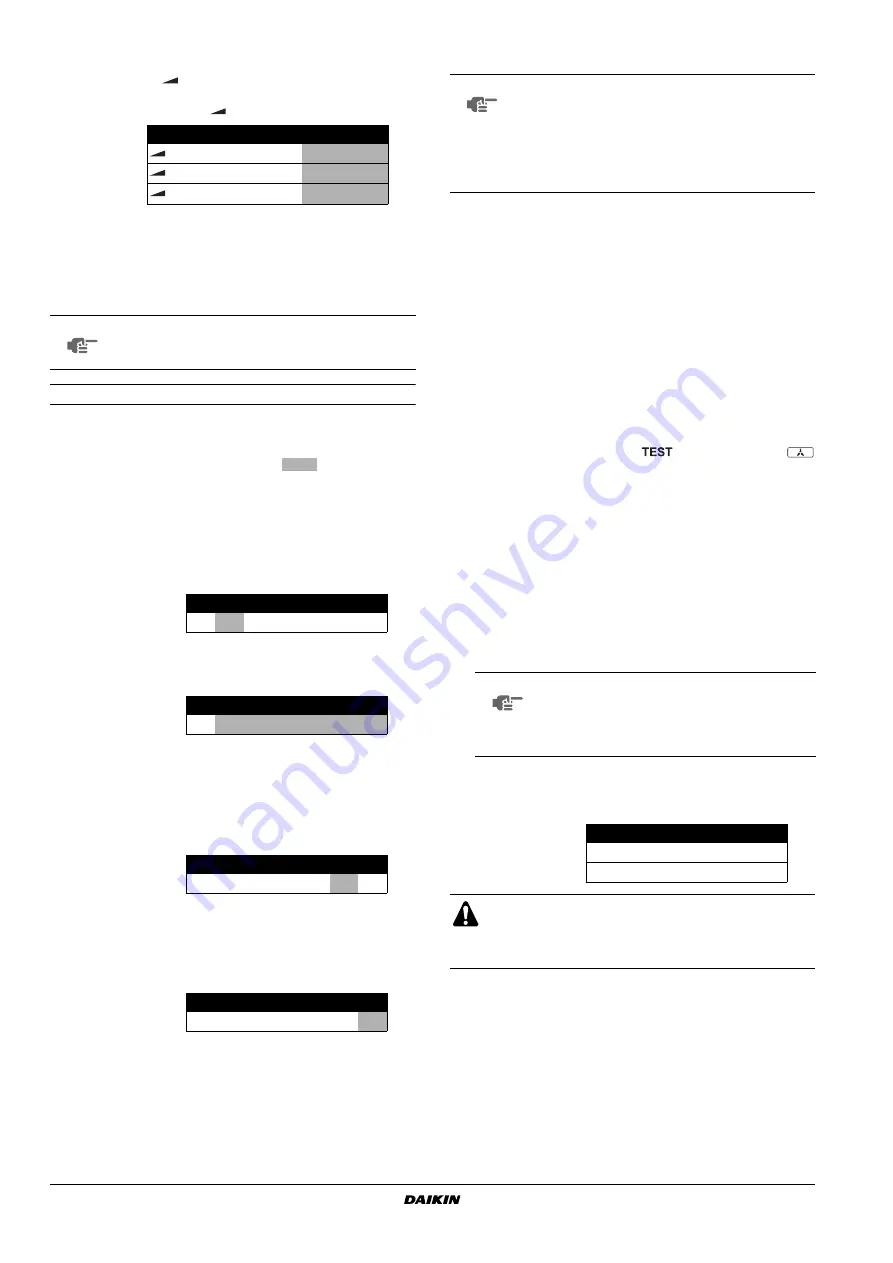
■
The led indication changes during this operation, but
that is not abnormal.
■
Please attach the front plate of the outdoor unit in
order to prevent electric shocks.
BS4 TEST
BS3 RETURN


