Installation manual
5
ERQ100~140A7V1B
Inverter condensing unit
4PW51321-1
5.1.
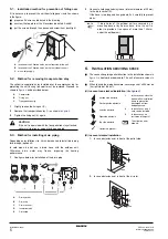
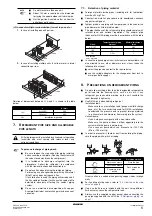
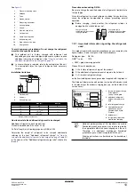
Installation method for prevention of falling over
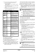
If it is necessary to prevent the unit from falling over, install as shown
in the figure.
■
prepare all 4 wires as indicated in the drawing
■
unscrew the top plate at the 4 locations indicated A and B
■
put the screws through the nooses and screw them back tight
A
location of the 2 fixation holes on the front side of the unit
B
location of the 2 fixation holes on the rear side of the unit
C
wires: field supply
5.2.
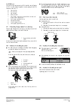
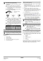
Method for removing transportation stay
The yellow transportation stay installed over the compressor leg for
protecting the unit during transport must be removed. Proceed as
shown in
and described below.
1
Slightly loosen the fixing nut (
2
Remove the transportation stay (
) as shown in
3
Tighten the fixing nut (
5.3.
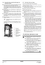
Method for installing drain piping
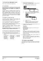
Depending on installation site, it may be required to install drain plug
for drainage (option kit).
In cold areas, do not use a drain hose with the outdoor unit.
Otherwise, drain water may freeze, impairing the heating
performance.
1
See figure below for installation of the drain plug.
2
Connect a field supplied vinyl hose (internal diameter of 25 mm)
to the drain socket (A).
If the hose is too long and hangs down, fix it carefully to prevent
kinks.
6.
I
NSTALLATION
SERVICING
SPACE
■
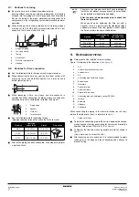
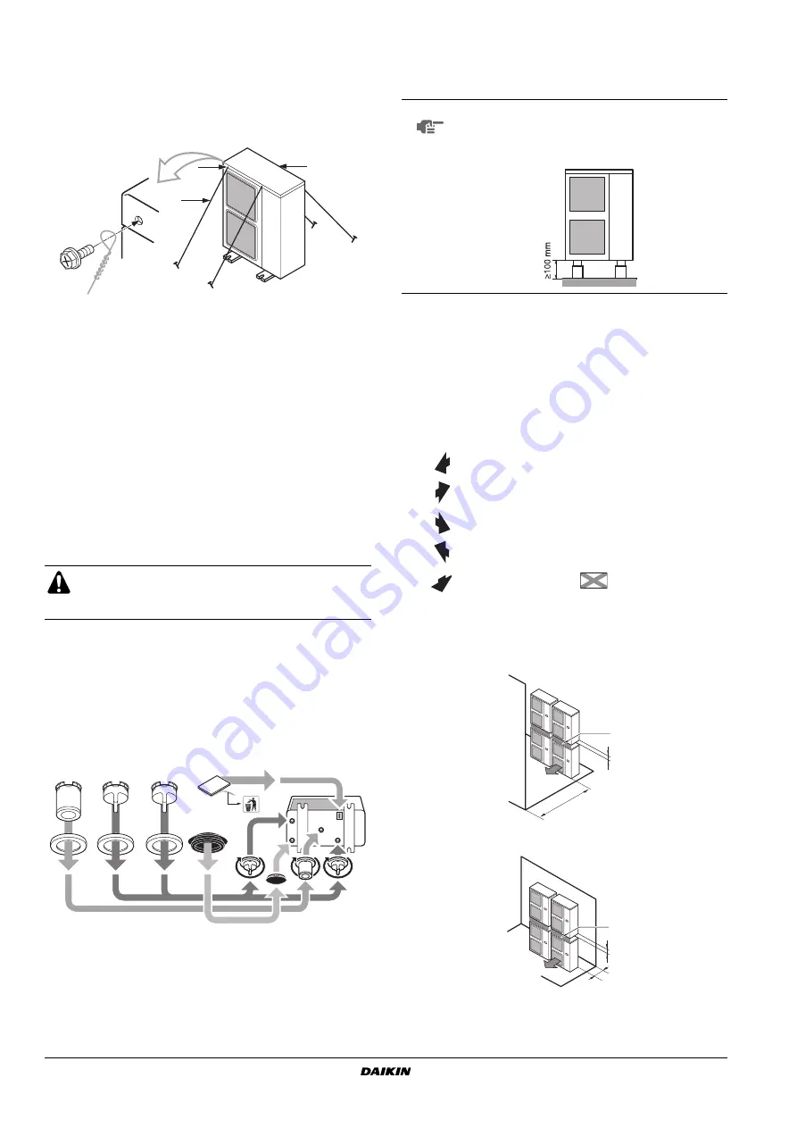
The connection piping outlet direction in the installation shown in
is frontward or downward. The unit of numeric values is
mm.
■
When routing the piping backward, secure space of
≥
250 mm on
the right side of the unit.
(A) In case of non-stacked installation
(B) In case of stacked installation
1.
In case obstacles exist in front of the outlet side.
2.
In case obstacles exist in front of the air inlet.
A
Compressor
B
Fixing nut
C
Transportation stay
CAUTION
If the unit is operated with the transportation stay attached,
abnormal vibration or noise may be generated.
A
Drain socket
B
Drain cap
C
Drain receiver
D
Insulation tape
E
Drain stop
C
B
A
A
E
E
B
A
B
D
C
C
C
B
A
B
D
NOTE
If drain holes of the outdoor unit are covered by a
mounting base or by floor surface, raise the unit in
order to provide a free space of more than 100 mm
under the outdoor unit.
Suction side obstacle
1
In these cases, close the
bottom of the installation
frame to prevent the
discharged air from
being bypassed
Discharge side obstacle
Left side obstacle
2
In these cases, only 2
units can be installed.
Right side obstacle
3
In these cases, no
restriction of height L1.
Top side obstacle
This situation is not
allowed
✓
Obstacle is present
≥
1000
100
A
≥
300
100
A

