ERQ100~140A7V1B
Inverter condensing unit
4PW51321-1
Installation manual
8
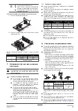
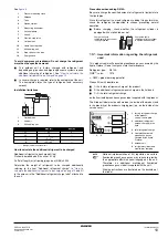
For ERQ140 only
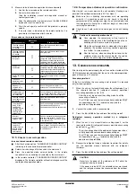
The size of the gas side stop valve is Ø15.9 while the inter-unit piping
is Ø19.1. Use the standard supplied accessory piping to make the
connection. See
9.1.
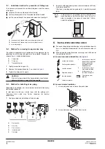
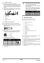
Preventing foreign objects from entering
Plug the pipe through-holes with putty or insulating material (field
supply) to stop up all gaps, as shown in the figure.
Insects or small animals entering the outdoor unit may cause a short
circuit in the electrical box.
9.2.
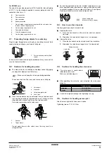
Cautions for handling stop valve
■
The stop valves for air handling unit-outdoor connecting piping
are closed at shipment from the factory.
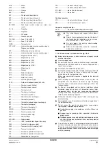
The names of parts of the stop valve are shown in the figure.
■
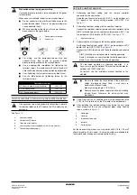
Since the side boards may be deformed if only a torque wrench
is used when loosening or tightening flare nuts, always lock the
stop valve with a wrench and then use a torque wrench.
Do not place wrenches on the valve cover.
Do not apply force on the valve cover, this may result in a
refrigerant leak.
■
For cooling operation under low ambient temperature or any
other operation under low pressure, apply silicon pad or similar
to prevent freezing of the gas stop valve flare nut (see figure).
Freezing of the flare nut may cause refrigerant leak.
9.3.
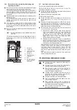
How to use the stop valve
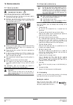
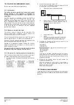
Use hexagonal wrenches 4 mm and 6 mm.
■
Opening the valve
1.
Place the hex wrench on the valve bar and turn counter-
clockwise.
2.
Stop when the valve bar no longer turns. It is now open.
■
Closing the valve
1.
Place the hex wrench on the valve bar and turn clockwise.
2.
Stop when the valve bar no longer turns. It is now closed.
9.4.
Cautions for handling the valve cover
■
The valve cover is sealed where
indicated by the arrow.
Take care not to damage it.
■
After operating the valve, be sure to tighten the valve cover
properly.
■
Check for refrigerant leakage after tightening the cap.
9.5.
Cautions for handling service port
After the work, tighten the valve cover in place.
Tightening torque: 11.5~13.9 N•m
A
Front connection
B
Rear connection
C
Side connection
D
Bottom connection
1
Gas line copper gasket supplied with the unit (make sure
to always use the copper gasket).
2
Gas line piping supplied with the unit
3
Gas piping (field supply)
4
Cut to the appropriate length.
5
Gas line piping supplied with the unit
1
Putty or insulating material (field
supply)
Make sure to keep the valve open during operation.
1
Service port
2
Stop valve
3
Field piping connection
4
Valve cover
1
Spanner
2
Torque wrench
1
3
4
1
2
1
2
Silicon sealing pad
(Make sure there is no gap)
Closing direction
Liquid side
Gas side
Tightening torque
Liquid pipe
13.5~16.5 N•m
Gas pipe
22.5~27.5 N•m

