background image


ERQ100~140A7V1B
Inverter condensing unit
4PW51321-1

Installation manual

18

5

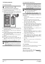
Measure to be taken when operation finishes abnormally

1.

Confirm the error code on the remote controller.

2.

Correct what is abnormal.
(See the installation manual and operation manual or
contact your dealer.)

3.

After the abnormality is corrected, press the 
button and reset the error code.

4.

Start the unit again to confirm that the problem is properly
solved.

5.

If no error code is indicated on the remote controller, it is
possible to start operation after 5 minutes.

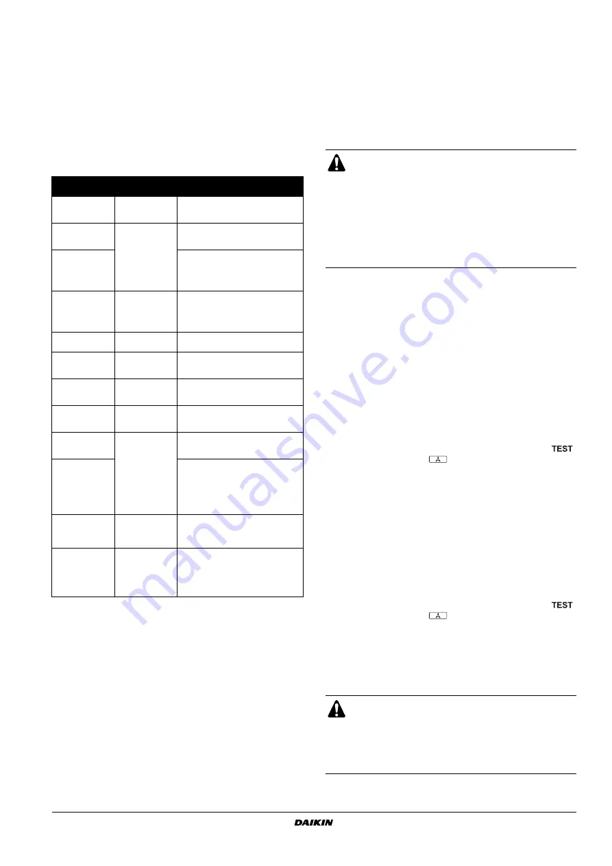
Error codes on the remote controller

12.5. Checks in normal operation

In case of wired remote controllers

After the check operation, "CHANGEOVER UNDER CONTROL"
is blinking in the connected remote controller.

Select an air handling unit to be used as the master unit.

Press the operation mode selector button in the remote
controller of the air handling unit selected as the master unit.

In that remote controller, "CHANGEOVER UNDER CONTROL"
disappears. That remote controller will control changeover of the
cooling/heating operation mode.

12.6. Temperature adjustment operation confirmation

After the test run is over, operate the unit normally. (Heating is not
possible if the outdoor temperature is 24°C or higher.)

Make sure the air handling and outdoor units are operating
normally (If a knocking sound can be heard in the liquid
compression of the compressor, stop the unit immediately and
then energize the heater for a sufficient length of time before
restarting the operation.)

Check to see if cold (or hot) air is coming out of the air handling
unit.

13. S

ERVICE


MODE


OPERATION

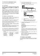
After turning on the power supply, the unit can not be started until the
H2P initialisation led, indicating that the unit is still under preparation,
goes off (maximum 12 minutes).

Vacuuming method

At the first installation, this vacuuming is not required. It is required
only for repair purposes.

1

When the unit is at a standstill and under the setting mode 2, set
the required function B (refrigerant recovery operation/
vacuuming operation) to 

 (ON).

-

After this is set, do not reset the setting mode 2 until the 
vacuuming is finished.

-

The H1P led is on and the remote controller indicates 


(test operation) and 

 (external control) and the 

operation will be prohibited.

2

Vacuum the system with a vacuum pump.

3

Press the 

 button and reset the setting mode 2.

Refrigerant recovery operation method by a refrigerant
reclaimer.

1

When the unit is at a standstill and in setting mode 2, set the
required function B (refrigerant recovery operation/vacuuming
operation) to 

 (ON).

-

The air handling unit and the outdoor unit expansion valves 
will fully open and some solenoid valves will open.

-

The H1P led is on and the remote controller indicates 


(test operation) and 

 (external control) and the 

operation will be prohibited.

2

Recover the refrigerant using a refrigerant reclaimer. For details,
see the operation manual delivered with the refrigerant
reclaimer.

3

Press the 

 button and reset the setting mode 2.

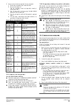
Installation error

Malfunction 

code

Remedial action

The stop valve of 
an outdoor unit is 
left closed.

E3

Open the stop valve on both the gas 
and liquid side.

The stop valve of 
an outdoor unit is 
left closed.

E4

F3

Open the stop valve on both the gas 
and liquid side.

Insufficient 
refrigerant

Check if the additional refrigerant 
charge has been finished correctly.
Recalculate the required amount of 
refrigerant from the piping length and 
add an adequate amount of refrigerant.

Refrigerant 
overcharge

E3

F6

Recalculate the required amount of 
refrigerant from the piping length and 
correct the refrigerant charge level by 
recovering any excessive refrigerant 
with a refrigerant recovery machine.

Insufficient supply 
voltage

U2

Check if the supply voltage is supplied 
properly.

The check 
operation is not 
performed.

U3

Perform the check operation.

No power is 
supplied to the 
outdoor unit.

U4

Check if the power wiring for the 
outdoor unit is connected correctly.

Improper type of 
air handling units 
are connected.

UA

Check the type of air handling units that 
are currently connected. If they are not 
proper, replace them with proper ones.

The stop valve of 
an outdoor unit is 
left closed.

UF

Open the stop valve on both the gas 
and liquid side.

The piping and 
wiring of the 
specified air 
handling unit are 
not connected 
correctly to the 
outdoor unit.

Confirm that the piping and wiring of the 
specified air handling unit are 
connected correctly to the outdoor unit.

Incorrect 
interconnections 
between units.

UH

Connect correctly the interconnections 
between units to the F1 and F2 (TO 
IN/D UNIT) terminals on the PC board 
in the outdoor unit.

Power supply 
cables are 
connected in the 
reverse phase 
instead of the 
normal phase.

U1

Connect the power supply cables in 
normal phase. Change any two of the 
three power supply cables (L1, L2, L3) 
to correct phase.

BS3  RETURN

Cautions for normal operation check

Once stopping, the compressor will not restart in
about 5 minutes even if the Run/Stop button of an air
handling unit in the same system is pressed.

When the system operation is stopped by the remote
controller, the outdoor units may continue operating
for a further 1 minute maximum.

After the test run, when handling the unit over to the
customer, make sure the electric box lid, the service
lid and the unit casing are all attached properly.

CAUTION

Never turn the power of the outdoor unit OFF while the
refrigerant is being recovered.

If the power is turned OFF, the solenoid valves are closed
and the refrigerant cannot be recovered from the outdoor
unit.

ON

BS1  MODE

ON

BS1  MODE

Summary of Contents for ERQ100A7V1B

Page 1: ...INSTALLATION MANUAL ERQ100A7V1B ERQ125A7V1B ERQ140A7V1B Inverter condensing unit ...

Page 2: ...H 0 L2 1 2 H 1 2 H L2 H 0 L1 1 2 H 1 2 H L1 H 0 L2 1 2 H 1 2 H L2 H L2 H L2 H L2 H L2 H L2 H L2 H 150 500 500 500 500 750 100 100 100 100 200 300 200 100 250 250 500 1000 1000 1000 500 500 500 500 1000 1000 1000 1000 500 500 1000 500 1000 1000 300 300 300 250 300 300 500 200 1000 1000 1000 1000 1000 1250 1500 1500 1000 1000 100 5 4 4 3 2 1 7 8 9 10 A D C B 5 6 11 7 6 1 2 3 4 5 6 7 9 8 12 13 10 11 ...

Page 3: ... gitt i henhold til bestemmelsene i 13 noudattaen määräyksiä 14 za dodržení ustanovení předpisu 15 prema odredbama 16 követi a z 17 zgodnie z postanowieniami Dyrektyw 18 în urma prevederilor 19 ob upoštevanju določb 20 vastavalt nõuetele 21 следвайки клаузите на 22 laikantis nuostatų pateikiamų 23 ievērojot prasības kas noteiktas 24 održiavajúc ustanovenia 25 bunun koşullarına uygun olarak 01 Note...

Page 4: ... here are divided into the following two types Both cover very important topics so be sure to follow them carefully Warning Ask your dealer or qualified personnel to carry out installation work Do not install the machine by yourself Improper installation may result in water leakage electric shocks or fire Perform installation work in accordance with this installation manual Improper installation m...

Page 5: ...e air handling and outdoor units power wire and connecting wire at least 1 meter away from televisions or radios to prevent image interference or noise Depending on the radio waves a distance of 1 meter may not be sufficient to eliminate the noise Do not rinse the outdoor unit This may cause electric shocks or fire Do not install the air conditioner in places such as the following Where there is m...

Page 6: ...ect an installation site where the following conditions are satisfied and that meets with your customer s approval Places which are well ventilated Places where the unit does not bother next door neighbours Safe places which can withstand the unit s weight and vibration and where the unit can be installed level Places where there is no possibility of flammable gas or product leak Places where serv...

Page 7: ...he drain water dripping 10 The equipment is not intended for use in a potentially explosive atmosphere 5 PRECAUTIONS ON INSTALLATION Check the strength and level of the installation ground so that the unit will not cause any operating vibration or noise after installation In accordance with the foundation drawing in the figure fix the unit securely by means of the foundation bolts Prepare four set...

Page 8: ...plied vinyl hose internal diameter of 25 mm to the drain socket A If the hose is too long and hangs down fix it carefully to prevent kinks 6 INSTALLATION SERVICING SPACE The connection piping outlet direction in the installation shown in figure 4 is frontward or downward The unit of numeric values is mm When routing the piping backward secure space of 250 mm on the right side of the unit A In case...

Page 9: ...ly into the system while the pump is not working Use a vacuum pump which can evacuate to 100 7 kPa 5 Torr 755 mm Hg In order to prevent dirt liquid or dust from entering the piping cure the piping with a pinch or taping Great caution is needed when passing copper tubes through walls For handling of stop valves refer to 9 3 How to use the stop valve on page 8 Only use the flare nuts included with t...

Page 10: ... install the connecting pipe to the unit in a downward direction make a knockout hole by penetrating the center area around the knockout hole using a Ø6 mm drill See figure 5 Cutting out the two slits makes it possible to install as shown in figure 5 Use a metal saw to cut out the slits After knocking out the knock out it is recommended to apply repair paint to the edge and the surrounding end sur...

Page 11: ... flare nut may cause refrigerant leak 9 3 How to use the stop valve Use hexagonal wrenches 4 mm and 6 mm Opening the valve 1 Place the hex wrench on the valve bar and turn counter clockwise 2 Stop when the valve bar no longer turns It is now open Closing the valve 1 Place the hex wrench on the valve bar and turn clockwise 2 Stop when the valve bar no longer turns It is now closed 9 4 Cautions for ...

Page 12: ...se a vacuum pump which can evacuate to 100 7 kPa 5 Torr 755 mm Hg 1 Evacuate the system from the liquid and gas pipes by using a vacuum pump for more than 2 hours and bring the system to 100 7 kPa After keeping the system under that condition for more than 1 hour check if the vacuum gauge rises or not If it rises the system may either contain moisture inside or have leaks 2 Following should be exe...

Page 13: ...ated greenhouse gases covered by the Kyoto Protocol Do not vent gases into the atmosphere Refrigerant type R410A GWP 1 value 1975 1 GWP global warming potential Please fill in with indelible ink the factory refrigerant charge of the product the additional refrigerant amount charged in the field and the total refrigerant charge on the fluorinated greenhouse gases label supplied with the product The...

Page 14: ...initial start up Setting the mode on page 16 set the required function A additional refrigerant charging operation to ON Then operation starts The blinking H2P led indicates test operation and the remote controller indicates test operation and external control 6 When the specified amount of refrigerant is charged push the button Then operation stops The operation automatically stops within 30 minu...

Page 15: ...ircuits must be interrupted Use only copper wires Do not turn on the main switch until all the wiring is completed Make sure that the main switch has a contact separation of at least 3 mm in all poles Never squeeze bundled cables into a unit Secure the electrical wiring with clamping material as shown in figure 9 so that it does not come in contact with the piping particularly on the high pressure...

Page 16: ...oper distance between power cable and control wiring 4 Clamp field supply 5 Stop valve mounting plate 6 Power cable 7 Ground cable yellow green 8 Fix the control wiring with the clamp 9 Control terminal block X2M 1 Knockout hole 2 Burr 3 Packing materials 2 3 1 Use a power wire pipe for the power wiring Outside the unit make sure the low voltage electric wiring i e for the remote control between u...

Page 17: ...rminals for connections to the power terminal block When none are available follow the instructions below Do not connect wiring of different thicknesses to the power terminal block Slack in the power wiring may cause abnormal heat When connecting wiring which is the same thickness do as shown in the figure below For wiring use the designated power wire and connect firmly then secure to prevent out...

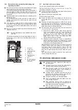
Page 18: ...ording to the instructions described in this manual according to the wiring diagrams and according to local and national regulations 4 Pipe sizes and pipe insulation Make sure that correct pipe sizes are installed and that the insulation work is properly executed 5 Additional refrigerant charge The amount of refrigerant to be added to the unit should be written on the included Added Refrigerant pl...

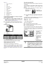
Page 19: ... 1 Led H1P H8P 2 Push button switches BS1 BS5 3 DIP switches 2 DS1 1 DS1 2 x OFF w ON c blinking For changing the set mode For field setting For field setting For test operation For resetting the address when the wiring is changed or when an additional air handling unit is installed NOTE If you get confused in the middle of the setting process push the button Then it returns to setting mode 1 H1P ...

Page 20: ...the sound of a magnetic solenoid valve may rise during this operation The following items are automatically checked Check for incorrect wiring Check if stop valves are open Check of refrigerant charge Automatic judgement of piping length 4 After the test operation maximum 30 minutes the unit automatically stops Check the operation results by the outdoor unit led indication H1P H2P H3P H4P H5P H6P ...

Page 21: ...e H1P led is on and the remote controller indicates test operation and external control and the operation will be prohibited 2 Recover the refrigerant using a refrigerant reclaimer For details see the operation manual delivered with the refrigerant reclaimer 3 Press the button and reset the setting mode 2 Installation error Malfunction code Remedial action The stop valve of an outdoor unit is left...

Page 22: ...steps 1 to 4 below and take whatever action is necessary to comply 1 Calculate the amount of refrigerant kg charged to each system separately 2 Calculate the smallest room volume m3 In a case such as the following calculate the volume of A B as a single room or as the smallest room 3 Calculating the refrigerant density using the results of the calculations in steps 1 and 2 above If the result of t...

Page 23: ...1 2 3 4 D E E E E E 9 A B C 2 2 3 2 4 7 2 9 3 2 3 5 6 1 4 8 3 2 3 16 V 1 2 3 4 230 V 6 5 TO IN D UNIT F1 F2 TO OUT D UNIT F1 F2 DS1 1 2 F1 F2 OUT IN ON OFF A2P X2M A1P A2P A4P X2M F1 F1 F2 F2 TO IN D UNIT C H SELECTOR X2M A C B A4P TO OUT D UNIT 4 A B C 1 3 2 5 F1 F2 1 2 3 4 5 8 11 12 9 10 13 14 ...

Page 24: ...4PW51321 1 Copyright Daikin ...

Reviews: