ERQ100~140A7V1B
Inverter condensing unit
4PW51321-1
Installation manual
6
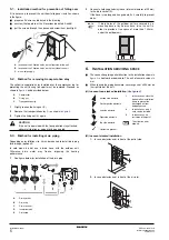
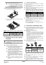
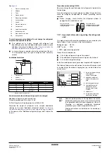
(C) In case of multiple-row installation (for roof top use, etc.)
1.
In case of installing one unit per row.
2.
In case of installing multiple units (2 units or more) in lateral
connection per row.
Relation of dimensions between H, A and L is shown in the table
below.
7.
R
EFRIGERANT
PIPE
SIZE
AND
ALLOWABLE
PIPE
LENGTH
7.1.
Selection of piping material
■
Foreign materials inside pipes (including oils for fabrication)
must be
≤
30 mg/10 m.
■
Construction material: phosphoric acid deoxidized seamless
copper for refrigerant.
■
Temper grade: use piping with temper grade in function of the
pipe diameter as listed in table below.
■
The pipe thickness of the refrigerant piping should comply with
relevant local and national regulations. The minimal pipe
thickness for R410A piping must be in accordance with the table
below.
O = Annealed
1/2H = Half hard
■
In case the required pipe sizes (inch sizes) are not available, it is
also allowed to use other diameters (mm sizes), taken the
following into account:
■
select the pipe size nearest to the required size.
■
use the suitable adapters for the change-over from inch to
mm pipes (field supply).
8.
P
RECAUTIONS
ON
REFRIGERANT
PIPING
■
Do not allow anything other than the designated refrigerant to
get mixed into the freezing cycle, such as air, etc. If any
refrigerant gas leaks while working on the unit, ventilate the
room thoroughly right away.
■
Use R410A only when adding refrigerant
Installation tools:
Make sure to use installation tools (gauge manifold charge
hose, etc.) that are exclusively used for R410A installations
to withstand the pressure and to prevent foreign materials
(e.g. mineral oils and moisture) from mixing into the system.
Vacuum pump:
Use a 2-stage vacuum pump with a non-return valve
Make sure the pump oil does not flow oppositely into the
system while the pump is not working.
Use a vacuum pump which can evacuate to –100.7 kPa
(5 Torr, –755 mm Hg).
■
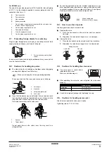
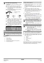
In order to prevent dirt, liquid or dust from entering the piping,
cure the piping with a pinch or taping.
Great caution is needed when passing copper tubes through
walls.
■
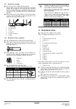
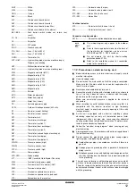
For handling of stop valves, refer to
■
Only use the flare nuts included with the unit. Using different
flare nuts may cause the refrigerant to leak.
■
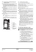
Always use the supplied copper gasket when connecting the
gas pipe supplied with the unit. See
NOTE
■
Do not stack more than one unit.
■
About 100 mm is required as the dimension
for laying the upper outdoor unit’s drain pipe.
■
Get the portion A sealed so that air from the
outlet does not bypass.
L
A (mm)
L
≤
H
0<L
≤
1/2H
250
1/2H<L
≤
H
300
H<L
Installation impossible
All field piping must be installed by a licensed refrigeration
technician and must comply with relevant local and
national regulations.
To persons in charge of piping work:
■
Be sure to open the stop valve after piping installing
and vacuuming is complete. (Running the system with
the valve closed may break the compressor.)
■
It is forbidden to discharge refrigerant into the
atmosphere. Collect the refrigerant in accordance
with the freon collection and destruction law.
■
Do not use flux when brazing the refrigerant piping.
For brazing, use phosphor copper brazing filler metal
(BCuP) which does not require a flux.
(If a chlorine flux is used, the piping will corrode, and if
the flux contains fluoride, it will cause the coolant oil to
deteriorate, adversely affecting the coolant piping
system.
■
Do not use materials not compatible with copper.
Example: Aluminium heat exchanger may be cause of
corrosion.
≥
1000
≥
200
≥
2000
≥
100
≥
1500
≥
600
≥
3000
A
H
L
Pipe Ø
Temper grade of piping
material
Minimal thickness t
(mm)
6.4 / 12.7
O
0.80
15.9
O
1
19.1
1/2H
1
Installation period
Protection method
More than a month
Pinch the pipe
Less than a month
Pinch or tape the
pipe
Regardless of the
period

