background image


Installation manual

14

ERX125~250A7W1B

Inverter condensing unit

4PW30064-1D

4

Final adjustment of the amount of refrigerant

When the unit displays an out of temperature range, the
charging of refrigerant can not be completed.

Out of outdoor temperature range

Complete the charging of refrigerant on another time when
the outdoor temperature is warmer than 0°C DB and colder
than 43°C DB.

Out of indoor temperature range

Complete the charging of refrigerant on another time when
the indoor temperature is warmer than 20°C DB and colder
than 32°C DB.

In this case, perform a test operation (as explained in the
chapter 

"12.4. Test operation" on page 16

) and the unit will work

properly. (The malfunction code 

U3

  will be displayed on the

remote controller (when attached).)

When the temperature has come in range (outdoor = 0~43°C,
indoor 

20~32°C), perform the overcharging judgement

procedure for completion of the refrigerant charging operation.

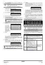
Overcharging judgement procedure

1.

Close all the front panels except the electric box front panel
and the lid on the side of the electric box.

2.

Turn on the power to the outdoor unit and all the connected
units.

3.

Press the 

 button once and set the setting

model H1P = OFF.

4.

Press and hold the 

 button down for 5 seconds.

5.

The system will start operating.

6.

Close all the front panels.
After operating for 40 minutes, the operation will stop
automatically.

7.

After the system has stopped operating, check the display
on the remote controller.

8.

If 

E3

F6

  or 

UF

  is displayed on the remote controller as a

result of the overcharge judging operation, recover 20% of
the charged amount of refrigerant and perform the
overcharge judgement procedure again.

When there is no more overcharging of refrigerant detected,
restart the refrigerant charging from the start as explained in

"11.4. Additional refrigerant charge" on page 12

.

11.5. Checks after adding refrigerant

Are the stop valves for both liquid and gas open?

Is the amount of refrigerant, that has been added, recorded?

12. B

EFORE


OPERATION

12.1.

Service precautions

Pay attention to the fan. It is dangerous to inspect the unit while the
fan is running. Be sure to turn off the main switch and to remove the
fuses from the control circuit located in the outdoor unit.

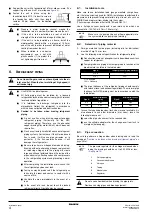
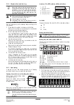
H1P

H2P

H3P

H4P

H5P

H6P

H7P

w c c c w x

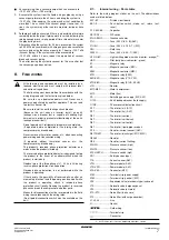
x

H1P

H2P

H3P

H4P

H5P

H6P

H7P

w c c c x w x

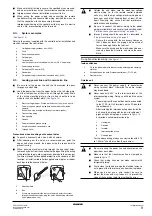
Make sure to open the stop valves after charging the
refrigerant.

Operating with the stop valves closed will damage the
compressor.

BS1  MODE

BS4  TEST

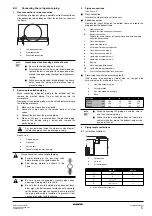
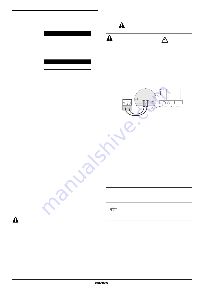
WARNING: ELECTRIC SHOCK 

Caution when performing service to inverter
equipment

1

Do not open the electric box cover for 10 minutes after
the power supply is turned off.

2

Measure the voltage between terminals on the
terminal block for power supply with a tester and
confirm that the power supply is shut off.

In addition, measure the points, as shown in the figure
below, with a tester and confirm that the voltage of the
capacitor in the main circuit is less than 50 V DC.

3

To  prevent damaging the PC-board, touch a
noncoated metal part to eliminate static electricity
before pulling out or plugging in connectors.

4

The performing of the service to the inverter
equipment must be started after the junction
connectors X1A, X2A, X3A, X4A (X3A and X4A are
for 14~18 unit type only) for the fan motors in the
outdoor unit are been pulled out. Be careful not to
touch the live parts.

(If a fan rotates due to strong wind, it may store
electricity in the capacitor or in the main circuit and
cause electric shock.)

5

After the service is finished, plug the junction
connector back in. Otherwise the error code 

E7

 will be

displayed on the remote controller and normal
operation will not be performed.

For details refer to the wiring diagram labeled on the back
of the electric box cover.

NOTE

Play it safe!

For protection of the PCB, touch the switch box casing
by hand in order to eliminate static electricity from your
body before performing service.

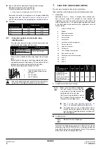
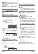
A2P

A2P

A1P

A3P

TP1 TP2

Summary of Contents for ERX125A7W1B

Page 1: ...INSTALLATION MANUAL ERX125A7W1B ERX200A7W1B ERX250A7W1B Inverter condensing unit ...

Page 2: ... d 500 mm e 100 mm a 200 mm b 300 mm e 400 mm A B C D A B 3 a 10 mm b 300 mm c 10 mm d 500 mm e 20 mm f 600 mm a 50 mm b 100 mm c 50 mm d 500 mm e 100 mm f 500 mm 4 a 10 mm b 300 mm c 10 mm d 300 mm e 20 mm f 500 mm a 50 mm b 100 mm c 50 mm d 100 mm e 100 mm f 500 mm 3 2 2 4 4 8 14 1 1 1500 500 100 100 11 13 6 9 8 1 2 4 3 5 14 15 16 12 11 10 7 13 14 3 5 4 2 1 7 8 9 6 10 11 12 1 2 12 15 1 2 4 5 6 3...

Page 3: ...iitä käytetään ohjeidemme mukaisesti 14 za předpokladu že jsou využívány v souladu s našimi pokyny odpovídají následujícím normám nebo normativním dokumentům 15 u skladu sa slijedećim standardom ima ili drugim normativnim dokumentom ima uz uvjet da se oni koriste u skladu s našim uputama 16 megfelelnek az alábbi szabvány ok nak vagy egyéb irányadó dokumentum ok nak ha azokat előírás szerint haszná...

Page 4: ...štelę 23 Maksimālais pieļaujamais spiediens PS K bar Minimālā maksimālā pieļaujamā temperatūra TS TSmin Minimālā temperatūra zemā spiediena pusē L C TSmax Piesātinātā temperatūra saskaņā ar maksimālo pieļaujamo spiedienu PS M C Dzesinātājs N Spiediena drošības ierīces iestatīšana P bar Izgatavošanas numurs un izgatavošanas gads skat modeļa izgatavotājuzņēmuma plāksnītie 24 Maximálny povolený tlak ...

Page 5: ...er condensing unit Installation manual READ THIS MANUAL ATTENTIVELY BEFORE STARTING UP THE UNIT DO NOT THROW IT AWAY KEEP IT IN YOUR FILES FOR FUTURE REFERENCE IMPROPER INSTALLATION OR ATTACHMENT OF EQUIPMENT OR ACCESSORIES COULD RESULT IN ELECTRIC SHOCK SHORT CIRCUIT LEAKS FIRE OR OTHER DAMAGE TO THE EQUIPMENT BE SURE ONLY TO USE ACCESSORIES MADE BY DAIKIN WHICH ARE SPECIFICALLY DESIGNED FOR USE ...

Page 6: ...tion site where sides A B C D have obstacles the wall heights of sides A C have no impact on service space dimensions Refer to figure 1 for impact of wall heights of sides B D on service space dimensions In case of an installation site where only the sides A B have obstacles the wall heights have no influence on any indicated service space dimensions 3 Make sure that there is no danger of fire due...

Page 7: ...re recommended to install the equipment and electric wires keeping proper distances away from stereo equipment personal computers etc See figure 2 In places with weak reception keep distances of 3 m or more to avoid electromagnetic disturbance of other equipment and use conduit tubes for power and transmission lines In heavy snowfall areas select an installation site where snow will not affect the...

Page 8: ...t infiltration of water coming from under the unit When installed in a corrosive environment use a nut with plastic washer 1 to protect the nut tightening part from rust Do not insert fingers rods or other objects into the air inlet or outlet When the fan is rotating at high speed it will cause injury Use R410A to add refrigerant All field piping must be installed by a licensed refrigeration techn...

Page 9: ...e knock holes wrap the wiring with protective tape to prevent damage Any gas remaining inside the stop valve may blow off the pinched piping causing damage or injury 1 Pinched piping 2 Stop valve 3 Service port 4 Point of melting the brazing metal Precautions when connecting field piping Perform brazing at the gas stop valve before brazing at the liquid stop valve Add brazing material as shown in ...

Page 10: ... the system passes the test If the pressure drops check where the nitrogen leaks from R Total length m of liquid piping size at Ø9 5 x0 059 Outdoor unit type Piping size mm Gas Liquid 125 Ø15 9 Ø9 5 200 Ø19 1 Ø9 5 250 Ø22 2 Ø9 5 Installation period Protection method More than a month Pinch the pipe Less than a month Pinch or tape the pipe Regardless of the period After all the piping has been conn...

Page 11: ...95 Resistor current limiting S1NPH Pressure sensor high S1NPL Pressure sensor low S1PH S2PH Pressure switch high SD1 Safety devices input T1A Current sensor A6P V1R Power module A4P V1R V2R Power module A3P X1A X4A Connector M1F X1M Terminal strip power supply X1M Terminal strip control A1P Y2E Expansion valve electronic type subcool Y1S Solenoid valve hotgas bypass Y2S Solenoid valve oil return Z...

Page 12: ...and lightning rods dangerous when struck by lightning due to abnormal rise in electrical potential in the grounding This unit uses an inverter and therefore generates noise which will have to be reduced to avoid interfering with other devices The outer casing of the product may take on an electrical charge due to leaked electrical current which will have to be discharged with the grounding Be sure...

Page 13: ... 4 Pipe opening 5 Conduit 6 Power wiring and ground wiring 7 Cut off the shaded zones before use 8 Through cover 1 Knockout hole 2 Burr 3 If there are any possibilities that small animals enter the system through the knockout holes plug the holes with packing materials to be prepared on site 2 3 1 Outside the unit make sure the weak low voltage electric wiring i e for the remote control between un...

Page 14: ...ply cord make sure that the current carrying conductors become taut before the earthing conductor Precautions when laying power wiring Do not connect wiring of different thicknesses to the power terminal block Slack in the power wiring may cause abnormal heat When connecting wiring which is the same thickness do as shown in the figure below For wiring use the designated power wire and connect firm...

Page 15: ...e specified amount of refrigerant in liquid state to the liquid pipe Since this refrigerant is a mixed refrigerant adding it in gas form may cause the refrigerant composition to change preventing normal operation Before charging check whether the refrigerant cylinder is equipped with a siphon tube or not Be sure to use tools exclusively for R410A to ensure required pressure resistance and to preve...

Page 16: ...op valve size Tightening torque N m Turn clockwise to close Shaft Cap valve lid Service port Valve body Hexagonal wrench Ø9 5 5 4 6 6 4 mm 13 5 16 5 11 5 13 9 Ø15 9 13 5 16 5 6 mm 23 0 27 0 Ø19 1 27 0 33 0 8 mm 22 5 27 5 Ø25 4 When charging a system charging over the permissible quantity can cause liquid hammer Always use protective gloves and protect your eyes when charging refrigerant When the r...

Page 17: ...turn to setting mode 1 H1P x OFF Setting mode 1 default system status H1P H2P H3P H4P H5P H6P H7P Default status normal x x w x x x x H1P H2P H3P H4P H5P H6P H7P w w w w w w w When charging in cooling mode the unit will stop operating when the required amount of refrigerant is charged H1P H2P H3P H4P H5P H6P H7P Pressure control for the first minute x c x x x x w Start up control for the next 2 mi...

Page 18: ...dding refrigerant Are the stop valves for both liquid and gas open Is the amount of refrigerant that has been added recorded 12 BEFORE OPERATION 12 1 Service precautions Pay attention to the fan It is dangerous to inspect the unit while the fan is running Be sure to turn off the main switch and to remove the fuses from the control circuit located in the outdoor unit H1P H2P H3P H4P H5P H6P H7P w c...

Page 19: ...tches LEDs and buttons Led state Throughout the manual the state of the LEDs is indicated as follows Setting the DIP switches Setting the push button switch BS1 5 Function of the push button switch which is located on the outdoor unit PCB A1P The figure shows state of the LED indications when the unit is shipped from the factory Check operation procedure 1 Turn the power on for the outdoor unit an...

Page 20: ...ing to the crank case heater 3 Make the field setting as needed using the push buttons on the PCB A1P of the outdoor unit Refer to Field setting on page 15 4 Set the check operation without initial refrigerant decision following setting mode 2 in the field setting and perform the check operation The system operates for 30 minutes and automatically stops the check operation If no malfunction code i...

Page 21: ...nction code displayed on the remote controller In case of a displayed malfunction code perform the following actions to correct the abnormality Error codes on the remote controller when a remote controller is connected After correcting the abnormality press the button and reset the malfunction code Carry out the test operation again and confirm that the abnormality is properly corrected Air handli...

Page 22: ...s or standards The following standards may be applicable if local regulations are not available This unit like other air conditioning systems uses R410A as refrigerant R410A itself is an entirely safe non toxic non combustible refrigerant Nevertheless care must be taken to ensure that air conditioning facilities are installed in a room which is sufficiently large This assures that the maximum conc...

Page 23: ...n a concentration in excess of the maximum concentration level then it will be necessary to revise the system Please consult your supplier 15 DISPOSAL REQUIREMENTS Dismantling of the unit treatment of the refrigerant of oil and of other parts must be done in accordance with relevant local and national legislation NOTES A Where there are no smaller room divisions B Where there is a room division bu...

Page 24: ...NOTES NOTES ...

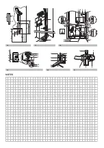
Page 25: ...21 1 2 3 4 5 19 L1 L2 L3 N 1 3 4 2 6 5 7 8 9 10 11 5 1 7 10 3 2 9 6 6 6 6 7 4 11 8 6 6 18 2 1 1 3 3 17 16 A A B C D 1 2 1 3 4 25 150 90 20 6 6 5 1 4 3 2 4 5 NOTES 16 17 18 19 20 21 ...

Page 26: ...4PW30064 1D Copyright Daikin ...

Reviews: