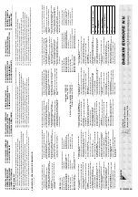
01
•
Maxim
um allo
wa
ble pressure (PS):
<K>
(bar)
•
Minim
um/maxim
um allo
wa
ble temper
ature (TS*):
* TSmin:
Minim
um temper
ature at lo
w pressure side:
<L>
(°C)
* TSmax:
Satur
ated temper
ature corresponding with the maxim
um
allo
wa
ble pressure (PS):
<M>
(°C)
•
Refr
iger
ant:
<N>
•
Setting of pressure saf
ety de
vice:
<P>
(bar)
•
Man
uf
actur
ing n
umber and man
uf
actur
ing y
ear
: ref
er to model
nameplate
02
•
Maximal zulässiger Dr
uc
k (PS):
<K>
(Bar)
•
Minimal/maximal zulässige
Temper
atur (TS*):
* TSmin:
Mindesttemper
atur auf der Niederdr
uc
kseite:
<L>
(°C)
* TSmax:
Sättigungstemper
atur die dem maximal zulässigen
Dr
uc
k (PS) entspr
icht:
<M>
(°C)
•
Kältemittel:
<N>
•
Einstellung der Dr
uc
k-Schutzv
orr
ichtung:
<P>
(Bar)
•
Herstellungsn
ummer und Herstellungsjahr
: siehe
Typenschild des
Modells
03
•
Pression maximale admise (PS):
<K>
(bar)
•
Tempér
ature minim
um/maxim
um admise (TS*):
* TSmin:
tempér
ature minim
um côté basse pression:
<L>
(°C)
* TSmax:
tempér
ature saturée correspondant à la pression
maximale admise:
<M>
(°C)
•
Réfr
igér
ant:
<N>
•
Réglage du dispositif de sécur
ité de pression:
<P>
(bar)
•
Numéro de f
abr
ication et année de f
abr
ication:
se repor
ter à la
plaquette signalétique du modèle
04
•
Maximaal toelaatbare dr
uk (PS):
<K>
(bar)
•
Minimaal/maximaal toelaatbare temperatuur (TS*):
* TSmin:
Minim
umtemper
atuur aan lagedr
ukzijde:
<L>
(°C)
* TSmax:
Verzadigde temper
atuur die o
vereenstemt met de
maximaal toelaatbare dr
uk (PS):
<M>
(°C)
•
Koelmiddel:
<N>
•
Instelling v
an dr
ukbe
veiliging:
<P>
(bar)
•
Fabr
icagen
ummer en f
abr
icagejaar
: zie naamplaat model
05
•
Presión máxima admisib
le (PS):
<K>
(bar)
•
Temper
atur
a mínima/máxima admisib
le (TS*):
* TSmin:
Temper
atur
a mínima en el lado de baja presión:
<L>
(°C)
* TSmax:
Temper
atur
a satur
ada correspondiente a la presión
máxima admisib
le:
<M>
(°C)
•
Refr
iger
ante:
<N>
•
Ajuste del presostato de segur
idad:
<P>
(bar)
•
Número de f
abr
icación y año de f
abr
icación:
consulte la placa de
especificaciones técnicas del modelo
06
•
Pressione massima consentita (PS):
<K>
(bar)
•
Temper
atur
a minima/massima consentita (TS*):
* TSmin:
temper
atur
a minima nel lato di bassa pressione:
<L>
(°C)
* TSmax:
temper
atur
a satur
a corr
ispondente alla pressione
massima consentita (PS):
<M>
(°C)
•
Refr
iger
ante:
<N>
•
Impostazione del dispositiv
o di controllo della pressione:
<P>
(bar)
•
Numero di ser
ie e anno di produzione:
fare r
ife
rimento alla
targhetta del modello
07
•
ª¤ÁÈÛÙË ÂÈÙÚÂfiÌÂÓË ›ÂÛË
(PS):
<K>
(bar)
•
∂Ï¿¯ÈÛÙË/̤ÁÈÛÙË ÂÈÙÚÂfiÌÂÓË ıÂÚÌÔÎÚ·Û›·
(TS*):
* TSmin:
∂Ï¿¯ÈÛÙË ıÂÚÌÔÎÚ·Û›· ÁÈ· ÙËÓ ÏÂ˘Ú¿ ¯·ÌËÏ‹˜
›ÂÛ˘:
<L>
(°C)
* TSmax:
∫ÔÚÂṲ̂ÓË ıÂÚÌÔÎÚ·Û›· Ô˘ ·ÓÙÈÛÙÔȯ› Ì ÙË
̤ÁÈÛÙË ÂÈÙÚÂfiÌÂÓË ›ÂÛË
(PS):
<M>
(°C)
•
æ˘ÎÙÈÎfi:
<N>
•
ƒ‡ıÌÈÛË Ù˘ ‰È¿Ù·Í˘ ·ÛÊ¿ÏÂÈ·˜ ›ÂÛ˘:
<P>
(bar)
•
∞ÚÈıÌfi˜ ηٷÛ΢‹˜ Î·È ¤ÙÔ˜ ηٷÛ΢‹˜: ·Ó·ÙÚ¤ÍÙ ÛÙËÓ
ÈӷΛ‰· ·Ó·ÁÓÒÚÈÛ˘ ÙÔ˘ ÌÔÓÙ¤ÏÔ˘
08
•
Pressão máxima per
mitida (PS):
<K>
(bar)
•
Temper
atur
as mínima e máxima per
mitidas (TS*):
* TSmin:
Temper
atur
a mínima em baixa pressão:
<L>
(°C)
* TSmax:
Temper
atur
a de satur
ação correspondente à pressão
máxima per
mitida (PS):
<M>
(°C)
•
Refr
iger
ante:
<N>
•
Regulação do dispositiv
o de segur
ança da pressão:
<P>
(bar)
•
Número e ano de f
abr
ico:
consultar a placa de especificações
da unidade
09
•
Мак
симально допу
стимое давление
(PS):
<K>
(
бар
)
•
Минимально/мак
симально допу
стимая темпер
атур
а
(TS*):
* TSmin:
Минимальная темпер
атур
а на стороне низк
ог
о
давления:
<L>
(°C)
* TSmax:
Темпер
атур
а кипения, соответств
ующая
мак
симально допу
стимому давлению
(PS):
<M>
(°C)
•
Хладаг
ент:
<N>
•
Настройка у
стройства защиты по давлению:
<P>
(
бар
)
•
Заво
дск
ой номер и г
од изг
отовления: смотрите паспортную
та
бличку мо
дели
10
•
Maks
. tilladt tr
yk (PS):
<K>
(bar)
•
Min./maks
. tilladte temper
atur (TS*):
* TSmin:
Min.
temper
atur på la
vtr
ykssiden:
<L>
(°C)
* TSmax:
Mættet temper
atur sv
arende til maks
. tilladte tr
yk (PS):
<M>
(°C)
•
Kø
lemiddel:
<N>
•
Indstilling af tr
yksikr
ingsudstyr
: <P>
(bar)
•
Produktionsn
ummer og fremstillingsår
: se modellens f
abr
iksskilt
11
•
Maximalt tillåtet tr
yc
k (PS):
<K>
(bar)
•
Min/max tillåten temper
atur (TS*):
* TSmin:
Minim
umtemper
atur på lågtr
yc
kssidan:
<L>
(°C)
* TSmax:
Mättnadstemper
atur som motsv
ar
ar maximalt tillåtet
tryc
k (PS):
<M>
(°C)
•
Köldmedel:
<N>
•
Inställning för tr
yc
ksäk
erhetsenhet:
<P>
(bar)
•
Tillv
er
kningsn
ummer och tillv
er
kningsår
: se modellens namnplåt
12
•
Maksimalt tillatt tr
ykk (PS):
<K>
(bar)
•
Minimalt/maksimalt tillatt temper
atur (TS*):
* TSmin:
Minim
umstemper
atur på la
vtr
ykkssiden:
<L>
(°C)
* TSmax:
Metningstemper
atur i samsv
ar med maksimalt tillatt
trykk (PS):
<M>
(°C)
•
Kjø
lemedium:
<N>
•
Innstilling a
v sikk
erhetsanordning f
or tr
ykk:
<P>
(bar)
•
Produksjonsn
ummer og produksjonsår
: se modellens mer
keplate
13
•
Suur
in sallittu paine (PS):
<K>
(bar)
•
Pienin/suur
in sallittu lämpötila (TS*):
* TSmin:
Alhaisin matalapainepuolen lämpötila:
<L>
(°C)
* TSmax:
Suur
inta sallittua painetta (PS) v
astaa
va
kyllästyslämpötila:
<M>
(°C)
•
Kylmäaine:
<N>
•
Va
rm
uuspainelaitteen asetus:
<P>
(bar)
•
Valmistusn
umero ja v
almistusvuosi:
katso mallin nimikilpi
14
•
Maximální přípustný tlak (PS):
<K>
(bar)
•
Minimální/maximální přípustná teplota (TS*):
* TSmin:
Minimální teplota na nízkotlaké straně:
<L>
(°C)
* TSmax:
Saturovaná teplota odpovídající maximálnímu
přípustnému tlaku (PS):
<M>
(°C)
•
Chladivo:
<N>
•
Nastavení bezpečnostního tlakového zařízení:
<P>
(bar)
•
Výrobní číslo a rok výroby: viz typový štítek modelu
15
•
Najveći dopušten tlak (PS):
<K>
(bar)
•
Najniža/najviša dopuštena temperatura (TS*):
* TSmin:
Najniža temperatura u području niskog tlaka:
<L>
(°C)
* TSmax:
Standardna temperatura koja odgovara najvećem
dopuštenom tlaku (PS):
<M>
(°C)
•
Rashladno sredstvo:
<N>
•
Postavke sigurnosne naprave za tlak:
<P>
(bar)
•
Proizvodni broj i godina proizvodnje: pogledajte natpisnu pločicu
modela
16
•
Legnagyobb megengedhető nyomás (PS):
<K>
(bar)
•
Legkisebb/legnagyobb megengedhető hőmérséklet (TS*):
* TSmin:
Legkisebb megengedhető hőmérséklet a kis nyomású
oldalon:
<L>
(°C)
* TSmax:
A legnagyobb megengedhető nyomásnak (PS)
megfelelő telítettségi hőmérséklet (PS):
<M>
(°C)
•
Hűtőközeg:
<N>
•
A
túlnyomás-kapcsoló beállítása:
<P>
(bar)
•
Gyártási szám és gyártási év: lásd a berendezés adattábláján
17
•
Maksymalne dopuszczalne ciśnienie (PS):
<K>
(bar)
•
Minimalna/maksymalna dopuszczalna temperatura (TS*):
* TSmin:
Minimalna temperatura po stronie niskociśnieniowej:
<L>
(°C)
* TSmax:
Temperatura nasycenia odpowiadająca maksymalnemu
dopuszczalnemu ciśnieniu (PS):
<M>
(°C)
•
Czynnik chłodniczy:
<N>
•
Nastawa ciśnieniowego urządzenia bezpieczeństwa:
<P>
(bar)
•
Numer fabryczny oraz rok produkcji: patrz tabliczka znamionowa
modelu
18
•
Presiune maximă admisibilă (PS):
<K>
(bar)
•
Temperatură minimă/maximă admisibilă (TS*):
* TSmin:
Temperatură minimă pe partea de presiune joasă:
<L>
(°C)
* TSmax:
Temperatura de saturaţie corespunzând presiunii
maxime admisibile (PS):
<M>
(°C)
•
Agent frigorific:
<N>
•
Reglarea dispozitivului de siguranţă pentru presiune:
<P>
(bar)
•
Numărul de fabricaţie şi anul de fabricaţie: consultaţi placa de
identificare a modelului
19
•
Maksimalni dovoljeni tlak (PS):
<K>
(bar)
•
Minimalna/maksimalna dovoljena temperatura (TS*):
* TSmin:
Minimalna temperatura na nizkotlačni strani:
<L>
(°C)
* TSmax:
Nasičena temperatura, ki ustreza maksimalnemu
dovoljenemu tlaku (PS):
<M>
(°C)
•
Hladivo:
<N>
•
Nastavljanje varnostne naprave za tlak:
<P>
(bar)
•
Tovarniška številka in leto proizvodnje: glejte napisno ploščico
20
•
Maksimaalne lubatud surve (PS):
<K>
(bar)
•
Minimaalne/maksimaalne lubatud temperatuur (TS*):
* TSmin:
Minimaalne temperatuur madalsurve küljel:
<L>
(°C)
* TSmax:
Maksimaalsele lubatud survele (PS) vastav küllastunud
temperatuur (PS):
<M>
(°C)
•
Jahutusaine:
<N>
•
Surve turvaseadme seadistus:
<P>
(bar)
•
Tootmisnumber ja tootmisaasta: vaadake mudeli andmeplaati
21
•
Мак
симално допу
стимо наляг
ане
(PS):
<K>
(bar)
•
Минимално/мак
симално допу
стима темпер
атур
а
(TS*):
* TSmin:
Минимална темпер
атур
а от стр
ана
та
на ниск
ото
наляг
ане
: <L>
(°C)
* TSmax:
Темпер
атур
а на насищане
, съответстваща на
мак
симално допу
стимото наляг
ане
(PS):
<M>
(°C)
•
Охладител
: <N>
•
Настройка на пре
дпазното у
стройство за наляг
ане
: <P>
(bar)
•
Фабричен номер и г
одина на произво
дство: вижте
табелка
та
на мо
дела
22
•
Maksimalus leistinas slėgis (PS):
<K>
(bar)
•
Minimali/maksimali leistina temperatūra (TS*):
* TSmin:
Minimali temperatūra žemo slėgio pusėje:
<L>
(°C)
* TSmax:
Prisotinta temperatūra, atitinkamti maksimalų leistiną
slėgį (PS):
<M>
(°C)
•
Šaldymo skystis:
<N>
•
Apsauginio slėgio prietaiso nustatymas:
<P>
(bar)
•
Gaminio numeris ir pagaminimo metai: žiūrėkite modelio
pavadinimo plokštelę
23
•
Maksimālais pieļaujamais spiediens (PS):
<K>
(bar)
•
Minimālā/maksimālā pieļaujamā temperatūra (TS*):
* TSmin:
Minimālā temperatūra zemā spiediena pusē:
<L>
(°C)
* TSmax:
Piesātinātā temperatūra saskaņā ar maksimālo
pieļaujamo spiedienu (PS):
<M>
(°C)
•
Dzesinātājs:
<N>
•
Spiediena drošības ierīces iestatīšana:
<P>
(bar)
•
Izgatavošanas numurs un izgatavošanas gads: skat. modeļa
izgatavotājuzņēmuma plāksnītie
24
•
Maximálny povolený tlak (PS):
<K>
(bar)
•
Minimálna/maximálna povolená teplota (TS*):
* TSmin:
Minimálna teplota na nízkotlakovej strane:
<L>
(°C)
* TSmax:
Nasýtená teplota korešpondujúca s maximálnym
povoleným tlakom (PS):
<M>
(°C)
•
Chladivo:
<N>
•
Nastavenie tlakového poistného zariadenia:
<P>
(bar)
•
Výrobné číslo a rok výroby: nájdete na výrobnom štítku modelu
25
•
İzin verilen maksimum basınç (PS):
<K>
(bar)
•
İzin verilen minimum/maksimum sıcaklık (TS*):
* TSmin:
Düşük basınç tarafındaki minimum sıcaklık:
<L>
(°C)
* TSmax:
İzin verilen maksimum basınca (PS) karşı gelen doyma
sıcaklığı (PS):
<M>
(°C)
•
Soğutucu:
<N>
•
Basınç emniyet düzeninin ayarı:
<P>
(bar)
•
İmalat numarası ve imalat yılı: modelin ünite plakasına bakın
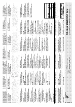
<K>
PS
40
bar
<L>
TSmin
–30
°C
<M>
TSmax
63
°C
<N>
R410A
<P>
40
bar
Jiro T
omita
Director Quality Assur
ance
Ostend,
3rd of J
a
n
uar
y 2008
CE - DECLARA
TION-OF-CONFORMITY
CE - K
ONFORMITÄTSERKLÄR
UNG
CE - DECLARA
TION-DE-CONFORMITE
CE - CONFORMITEITSVERKLARING
CE - DECLARA
CION-DE-CONFORMID
AD
CE - DICHIARAZIONE-DI-CONFORMIT
A
CE - ¢H§ø™H ™YMMOPºø™H™
CE - DECLARAÇÃO-DE-CONFORMID
ADE
СЕ - ЗАЯВЛЕНИЕ-О-СОО
ТВЕТСТВИИ
CE - OPFYLDELSESERKLÆRING
CE - FÖRSÄKRAN-OM-ÖVERENSTÄMMELSE
CE - ERKLÆRING OM-SAMSV
AR
CE - ILMOITUS-YHDENMUKAISUUDEST
A
CE -
PROHLÁŠENÍ-O-SHODĚ
CE -
IZJA
VA-O-USKLAĐENOSTI
CE - MEGFELELŐSÉGI-NYILA
TKOZA
T
CE -
DEKLARACJA-ZGODNOŚCI
CE -
DECLARAŢIE-DE-CONFORMIT
A
TE
CE - I
ZJA
VA
O SKLADNOSTI
CE -
VA
ST
A
V
USDEKLARA
TSIOON
CE -
ДЕКЛАР
А
ЦИЯ-ЗА
-СЪО
ТВЕТСТВИЕ
CE -
A
TITIKTIES-DEKLARACIJA
CE -
AT
BILSTĪBAS-DEKLARĀCIJA
CE -
VYHLÁSENIE-ZHODY
CE - UYUMLULUK-BİLDİRİSİ
01
a
continuation of pre
vious page:
02
d
F
or
tsetzung der vorher
igen Seite:
03
f
suite de la page précédente:
04
l
v
er
volg v
an v
or
ige pagina:
05
e
continuación de la página anter
ior
:
06
i
continua dalla pagina precedente:
07
g
Û˘Ó¤¯ÂÈ· ·fi ÙËÓ ÚÔËÁÔ‡ÌÂÓË ÛÂÏ›‰·
:
08
p
continuação da página anter
ior
:
09
u
про
до
лж
ение пре
дыдущей стр
аницы
:
10
q
fo
rtsat fra f
orr
ige side:
11
s
fo
rtsättning från föregående sida:
12
n
fo
rtsettelse fr
a f
orr
ige side:
13
j
jatk
oa edelliseltä sivulta:
14
c
pokračování z předchozí strany
:
15
y
nastavak s prethodne stranice
:
16
h
folytatás az előző oldalról
:
17
m
ciąg dalszy z poprzedniej strony
:
18
r
continuarea paginii anterioare
:
19
o
nadaljevanje s prejšnje strani
:
20
x
eelmise lehekülje järg:
21
b
про
дълж
ение от пре
дх
одна
та
стр
аница:
22
t
ankstesnio puslapio tęsinys:
23
v
iepriekšējās lappuses turpinājums:
24
k
pokračovanie z predchádzajúcej strany
:
25
w
önceki sayfadan devam
01
Design Specifi
cations of the models to whic
h this declaration relates:
02
K
onstruktionsdaten der Modelle auf die sic
h diese Erklärung bezieht:
03
Spécifications de conception des modèles auxquels se rapporte cette déc
laration:
04
Ontwerpspecifi
caties v
an de modellen waarop dez
e verklaring betrekking heeft:
05
Especifi
caciones de diseño de los modelos a los cuales hace ref
erencia
esta declaración:
06
Specifi
che di pr
og
etto dei modelli cui fa rif
erimento la presente dic
hiarazione:
07
¶ÚԉȷÁڷʤ˜ ™¯Â‰È·ÛÌÔ‡ ÙˆÓ ÌÔÓÙ
¤ÏˆÓ Ì ٷ ÔÔ›· Û¯ÂÙ›˙ÂÙ·È Ë ‰‹ÏˆÛË:
08
Especifi
cações de pr
ojecto dos modelos a que se aplica esta dec
laração:
09
Проектные х
арактеристики мо
делей,
к к
оторым относится
настоящее заявление:
10
T
ypespecifi
kationer for de modeller
, som denne erklæring vedrører:
11
Designspecifi
kationer för de modeller som denna deklaration gäller:
12
K
onstruksjonsspesifi
kasjoner for de modeller som berøres a
v denne deklarasjonen:
13
Tätä ilmoitusta k
oske
vien mallien rakennemäärittel
y:
14
Specifikace designu modelů, ke kterým se vztahuje toto prohlášení:
15
Specifikacije dizajna za modele na koje se ova izjava odnosi:
16
A
jelen nyilatkozat tárgyát képező modellek tervezési jellemzői:
17
Specyfikacje konstrukcyjne modeli, których dotyczy deklaracja:
18
Specificaţiile de proiectare ale modelelor la care se referă această declaraţie:
19
Specifikacije tehničnega načrta za modele, na katere se nanaša ta deklaracija:
20
Deklaratsiooni alla kuuluvate mudelite disainispetsifikatsioonid:
21
Проектни спецификации на мо
делите,
за к
оито се отнася декларацията:
22
Konstrukcinės specifikacijos modelių, kurie susiję su šia deklaracija:
23
To
modeļu dizaina specifikācijas, uz kurām attiecas šī deklarācija:
24
Konštrukčné špecifikácie modelu, ktorého sa týka toto vyhlásenie:
25
Bu bildirinin ilgili olduğu modellerin T
asarım Özellikleri:
2PW40200-4B
01
Name and address of the Notified body that judged positiv
ely on
compliance with the Pressure Equipment Directiv
e:
<Q>
02
Name und Adresse der benannten Stelle
, die positiv unter
Einhaltung der Dr
uc
kanlagen-Richtlinie ur
teilte:
<Q>
03
Nom et adresse de l'organisme notifi
é qui a év
alué positiv
ement la
conf
or
mité à la directiv
e sur l’équipement de pression:
<Q>
04
Naam en adres v
an de aangemelde instantie die positief geoordeeld
heeft o
ver de conf
or
miteit met de Richtlijn Dr
ukappar
atuur
: <Q>
05
Nombre y dirección del Organismo Notifi
cado que juzgó
positiv
amente el cumplimiento con la Directiv
a en mater
ia de
Equipos de Presión:
<Q>
06
Nome e indir
izz
o dell’Ente r
iconosciuto che ha r
iscontr
ato la
conf
or
mità alla Direttiv
a sulle apparecchiature a pressione:
<Q>
07
ŸÓÔÌ· Î·È ‰È‡ı˘ÓÛË ÙÔ˘ KÔÈÓÔÔÈË̤ÓÔ˘ ÔÚÁ·ÓÈÛÌÔ‡ Ô˘
·ÂÊ¿ÓıË ıÂÙÈο ÁÈ· ÙË Û˘ÌÌfiÚʈÛË ÚÔ˜ ÙËÓ √‰ËÁ›·
∂ÍÔÏÈÛÌÒÓ ˘fi ¶›ÂÛË
: <Q>
08
Nome e mor
ada do organismo notificado
, que a
valiou
fa
vo
ra
velmente a conf
or
midade com a directiv
a sobre equipamentos
pressur
izados:
<Q>
09
Название и адрес орг
ана те
хническ
ой эк
спертизы, принявшег
о
по
ло
жительное решение о соответствии Директиве об
обор
удовании по
д давлением:
<Q>
10
Na
vn og adresse på bem
yndiget organ, der har f
oretaget en positiv
bedø
mmelse af
, at udstyret le
ver op til kr
av
ene i PED (Direktiv f
or
Tr
ykbærende Udstyr):
<Q>
11
Namn och adress för det anmälda organ som godkänt uppfyllandet
av
tr
yc
kutr
ustningsdirektiv
et:
<Q>
12
Na
vn på og adresse til det autor
iser
te organet som positivt bedø
mte
samsv
ar med direktiv
et f
or tr
ykkutstyr (Pressure Equipment
Directiv
e):
<Q>
13
Sen ilmoitetun elimen nimi ja osoite
, joka teki m
yönteisen päätöksen
painelaitedirektiivin noudattamisesta:
<Q>
14
Název a adresa informovaného orgánu, který vydal pozitivní
posouzení shody se směrnicí o tlakových zařízeních:
<Q>
15
Naziv i adresa prijavljenog tijela koje je donijelo pozitivnu prosudbu o
usklađenosti sa Smjernicom za tlačnu opremu:
<Q>
16
A n
yomástar
tó berendezésekre v
onatk
ozó irán
yelvnek v
aló
megf
elelŒséget igaz
oló bejelentett sz
er
ve
zet ne
ve
és címe:
<Q>
17
Nazwa i adres Jednostki notyfikowanej, która wydała pozytywną
opinię dotyczącą spełnienia wymogów Dyrektywy dot. Urządzeń
Ciśnieniowych:
<Q>
18
Denumirea şi adresa organismului notificat care a apreciat pozitiv
conformarea cu Directiva privind echipamentele sub presiune
: <Q>
19
Ime in naslov organa za ugotavljanje skladnosti, ki je pozitivno ocenil
združljivost z Direktivo o tlačni opremi:
<Q>
20
Teavitatud organi, mis hindas Surveseadmete Direktiiviga ühilduvust
positiivselt, nimi ja aadress:
<Q>
21
Наименование и адрес на упълномощения орг
ан, к
ойто се е
произнесъл по
ло
жително относно съвместимостт
а с
Директива
та
за обор
удване по
д наляг
ане:
<Q>
22
Atsakingos institucijos, kuri davė teigiamą sprendimą pagal slėginės
įrangos direktyvą pavadinimas ir adresas:
<Q>
23
Sertifikācijas institūcijas, kura ir devusi pozitīvu slēdzienu par
atbilstību Spiediena Iekārtu Direktīvai, nosaukums un adrese:
<Q>
24
Názov a adresa certifikačného úradu, ktorý kladne posúdil zhodu so
smernicou pre tlakové zariadenia:
<Q>
25
Basınçlı
Teçhizat Direktifine uygunluk hususunda olumlu olarak
değerlendirilen Onaylanmış kuruluşun adı ve adresi
: <Q>
<Q>
AIB VINÇO
TTE
INTERNA
TIONAL
A
ven
ue du Roi 157
B-1190 Brussels,
Belgium


