Installation manual
6
ERX125~250A7W1B
Inverter condensing unit
4PW30064-1D
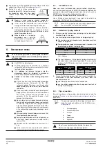
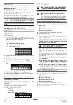
4.2 How to calculate the additional refrigerant to be charged
Additional refrigerant to be charged R (kg)
R should be rounded off in units of 0.1 kg
Determine the weight of refrigerant to be charged additionally
referring to the item
"Additional refrigerant charge" on page 12
and fill in the amount on the wiring diagram attached to the unit.
4.3 Diameters
6.5.
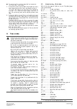
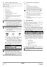
Protection against contamination when
installing pipes
-
Take measures to prevent foreign materials like moisture and
contamination from mixing into the system.
-
Great caution is needed when passing copper tubes through
walls.
-
Block all gaps in the holes for passing out piping and wiring
using sealing material (field supply). (The capacity of the unit
will drop and small animals may enter the machine.)
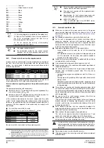
Example: passing piping out through the front
7.
L
EAK
TEST
AND
VACUUM
DRYING
The units were checked for leaks by the manufacturer.
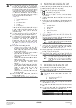
After connecting the field piping, perform the following inspections.
1
Preparations
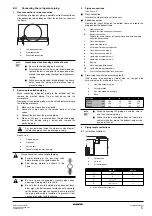
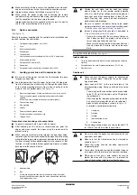
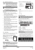
Referring to
, connect a nitrogen tank, a cooling tank,
and a vacuum pump to the outdoor unit and perform the
airtightness test and the vacuum drying. The stop valve and
valves A and B in
should be open and closed as shown
in the table below when performing the airtightness test and
vacuum drying.
2
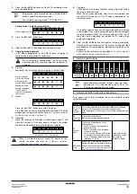
Airtightness test and vacuum drying
■
Airtightness test:
Pressurize the liquid and gas pipes to 4.0 MPa (40 bar) (do not
pressurize more than 4.0 MPa (40 bar)). If the pressure does not
drop within 24 hours, the system passes the test. If the pressure
drops, check where the nitrogen leaks from.
R= (Total length (m) of liquid piping size at Ø9.5) x0.059
Outdoor unit type
Piping size (mm)
Gas
Liquid
125
Ø15.9
Ø9.5
200
Ø19.1
Ø9.5
250
Ø22.2
Ø9.5
Installation period
Protection method
More than a month
Pinch the pipe
Less than a month
Pinch or tape the pipe
Regardless of the period
After all the piping has been connected, make sure there is
no gas leak. Use nitrogen to perform a gas leak check.
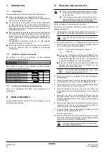
1
2
3
1
Plug the areas marked with "
".
(When the piping is routed from the
front panel.)
2
Gas side piping
3
Liquid side piping
1
Pressure reducing valve
2
Nitrogen
3
Measuring instrument
4
Tank (siphon system)
5
Vacuum pump
6
Charge hose
7
Service port for adding refrigerant
8
Gas line stop valve
9
Liquid line stop valve
10
Outdoor unit
11
To air handling unit evaporator
12
Stop valve service port
13
Dotted lines represent on site piping
14
Valve B
15
Valve C
16
Valve A
State
of the valves A and B
and the stop valve
Valve
A
Valve
B
Valve
C
Liquid
side
stop
valve
Gas
side
stop
valve
Performing the
airtightness test and
vacuum drying
(Valve A must always be
shut. Otherwise the
refrigerant in the unit will
pour out.)
Close
Open
Open
Close
Close
NOTE
Make sure to perform airtightness
test and vacuum drying using the
service ports of the stop valves of the
liquid side and of the gas side.
(For the service port location, refer to
the "Caution" label attached on the
front panel of the outdoor unit.)
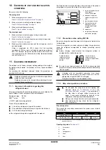
■
See
"11.3. Stop valve operation procedure" on
for details on handling the stop valve.
■
To prevent entry of any contamination and to
prevent insufficient pressure resistance, always
use the special tools dedicated for working with
R410A refrigerant.
NOTE
Make sure to use nitrogen gas.


