Wiring Diagrams
ESIE13-02
Part 1 – System Outline
34
3
11
4
5
3.2
Overview Switch Box
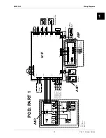
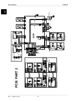
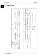
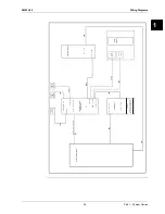
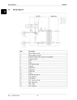
The next two figures ("PCB: part 1" and "PCB: part 2") show the wiring diagram of the hybrid PCB. The
different components are mentioned either on "PCB: part 1" or on "PCB: part 2”. The legend that is
attached mentions the description of each part number and can help to understand these two figures.
Some additional information on the PCB figures:
The
contacts S1S, S2S and S3S
, shown on PCB PART 1, fulfil the following functions:
S1S: Preferential kWh rate: can force the outdoor heat pump to switch off.
S2S: Electric power meter pulse input (for the purpose of energy metering).
S3S: Gas meter pulse input (for the purpose of energy metering).
The
user interface
(A2P, see drawing "PCB: PART 1"): is delivered as an accessory within the
unit. The connection diagram (see further) shows how to connect it to the PCB.
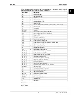
Part number
Description
A4P
Digital I/O PCB, receiver PCB (wireless ON/OFF thermostat, PC= power circuit)
(optional)
A8P
Demand PCB (optional)
TR1, TR2
Power supply transformer
A1P
Main PCB (hydro)
X*Y
Connector
X*M
Terminal strip
A1P
TR2
X5M
X2M
A8P
A4P
X6Y
TR1
X1M

