ESIE13-02
Wiring Diagrams
35
Part 1 – System Outline
3
1
4
5
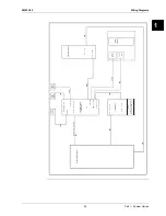
B1L
only for instant hot water
(recirculation) without tank
56
X5M
ext. ambient
sensor option
(indoor or
outdoor)
A8P
1
2
X801M
345
DS1
ON OFF
1234
Demand PCB
3
X5M
4
9
10
1
2
A2P
1
2
X5M
P1
P1
P2
P2
A2P
User interface
Remote
user interface
A1P
Only for demand PCB option
only for domestic
hot water tank option
Electric pulse meter input:
5 V DC pulse detection
(voltage supplied by PCB)
Preferential kWh rate PS contact:
16 V DC detection
(voltage supplied by PCB)
Power limitation
digital inputs:
12 V DC / 12 mA detection
(voltage supplied by PCB)
X5
Switch
box
Switch box
Gas pulse meter input:
5 V DC pulse detection
(voltage supplied by PCB)
7
8
A4P
SS1
ON OFF
12
A3P
only for solar option
13a
X2M
21
28
29
Alarm
output (*)
Space C/H
On/OFF output (*)
Options: solar pump connection, alarm output, On/OFF output
X1
X2
X3
X4
Y3
Y4
YC
Y2
Y1
PHC1
Only for digital I/O PCB option
Digital I/O PCB
GAS BOILER
*HYKOMB*
(*)
Max. load
0.3 A - 250 V AC
Min. load
20 mA - 5 V DC
4
4
X6A:1
2
2
R3T
-t°
2
X5A:1
2
R2T
-t°
X8A:1
X7A:1
R4T
-t°
X9A:1
2
R5T
-t°
5
6
4
3
2
X40A:1
10
11
12
9
8
7
6
5
4
3
5
6
4
3
X33A:1
3
2
X4A:1
8
7
2
X80A:1
S6S
S7S
S8S
S9S
R1T
-t°
6
5
4
3
2
X85A:1
X22A:1
2
X18A:1
2
R1T
-t°
R1T
-t°
2
R6T
-t°
R5T
-t°
S1S
S2S
S3S
CN2:1
2
3
4
5
6
CN1:1
3
F2U
F1U
BSK
KFR
KCR
KHUR
KHR
M4S
M
X70A:1
2
3
5
6
4
7
8
4
3
X39A:1
2
4
X24A.5
X2M.9
A1P
A2P
A8P
A4P
PCB: P
ART 1


