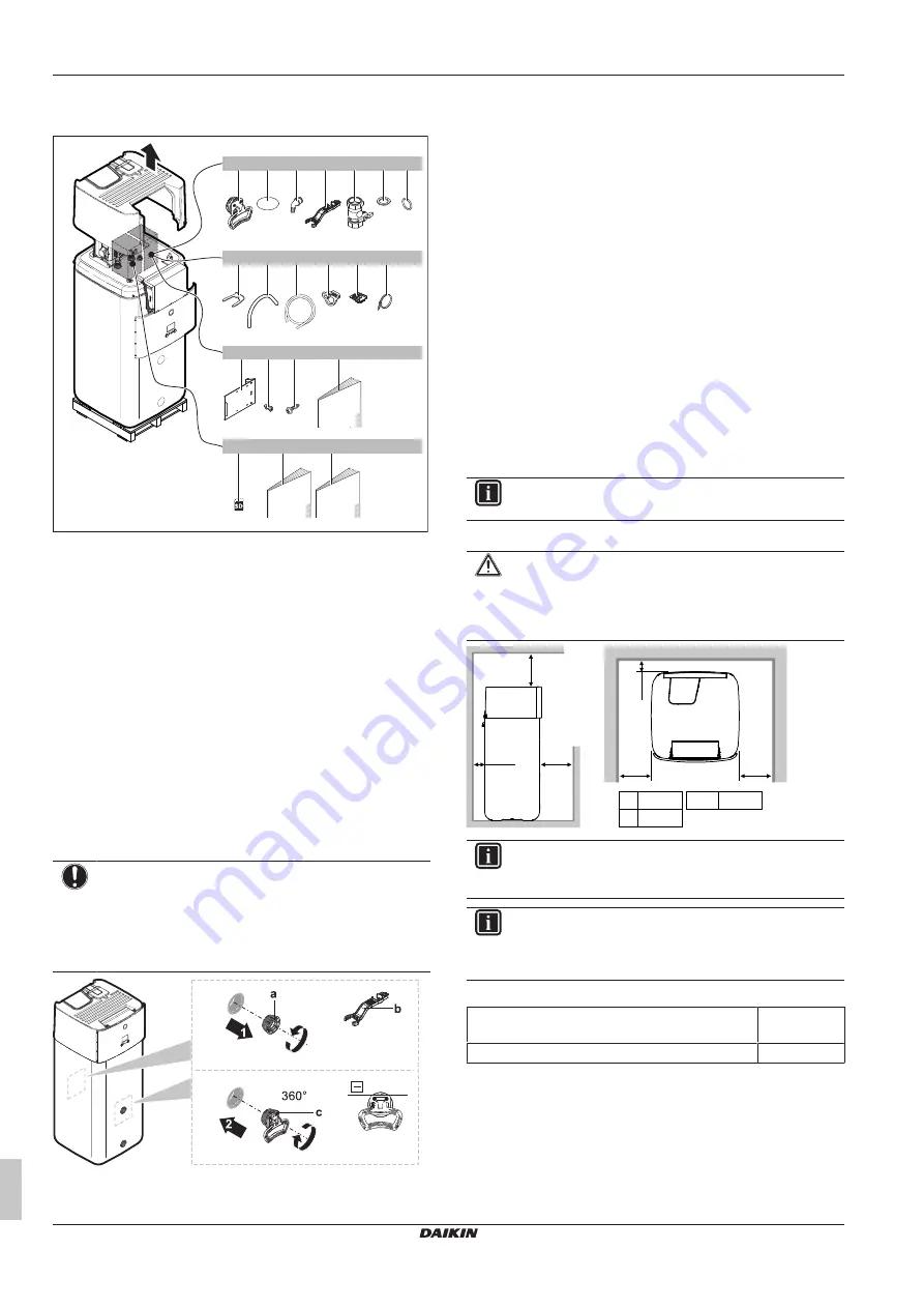
4 Unit installation
Installation manual
6
ETSH/X(B)16P30+50EF
Daikin Altherma 3 H HT ECH
₂
O
4P679468-1A – 2022.07
3.1.1
To remove the accessories from the
indoor unit
1×
1×
1×
1×
1×
1×
h
i
j
m
o
n
3×
1×
1×
2×
2×
a
b
c
d
e
f
1×
s
1×
t
1×
q
2×
1×
g
1×
1 ×
7
k
l
20×
2×
p
r
a
Handles (only required for transport)
b
Thread cover
c
Spillover connector
d
Assembly wrench
e
Shut-off valve
f
Flat gasket
g
O‑ring
h
Securing clip
i
Venting hose
j
Drain pan hose
k
Drain pan hose clamp
l
Cable fixation for strain relief
m
Cable tie
n
Switch box metal insert
o
Screw for switch box metal insert
p
Top cover screws
q
General safety precautions
r
WLAN cartridge
s
Indoor unit installation manual
t
Operation manual
3.1.2
To handle the indoor unit
Use the handles at the back and at the front to carry the unit.
NOTICE
The indoor unit is top-heavy as long as the storage tank is
empty. Secure the unit accordingly and only transport by
using the handles.
If optional Backup Heater (EKECBU*) is installed, see the
installation manual of the Backup Heater.
a
Screw plug
b
Assembly wrench
c
Handle
1
Open the screw plugs on the front and back of the tank.
2
Attach the handles horizontally and turn by 360°.
3
Use the handles to carry the unit.
4
After carrying the unit remove the handles, add the screw plugs
again and insert the thread covers on the plugs.
4
Unit installation
4.1
Preparing the installation site
4.1.1
Installation site requirements of the
indoor unit
▪ The indoor unit is designed for indoor installation only and for the
following ambient temperatures:
▪ Space heating operation: 5~30°C
▪ Space cooling operation: 5~35°C
▪ Domestic hot water production: 5~35°C. If EKECBUAF6V is
installed, ambient temperature is limited to 5~32°C.
INFORMATION
Cooling is only applicable in case of reversible models.
▪ Mind the following spacing installation guidelines:
CAUTION
Install the indoor unit at a minimum distance of 1 m from
other heat sources (>80°C) (e.g. electrical heater, oil
heater, chimney) and combustible materials. Otherwise the
unit may be damaged or in extreme cases catch fire.
≥500
00
1≥
≥100
08
4≥
[
]
mm
a
b
a
≥100
a+b
≥600
b
≥300
INFORMATION
Serviceability may be impacted, if the indicated clearances
cannot be maintained.
INFORMATION
If you have limited installation space, do the following
before installing the unit in its final position:
connect the drain hose to the drain"
▪ Mind the measurement guidelines:
Maximum height difference between indoor unit and
outdoor unit
10 m
Maximum total water piping length
50 m
(a)
(a)
Precise water piping length can be determined using the Hydronic
Piping Calculation tool. The Hydronic Piping Calculation tool is
part of the Heating Solutions Navigator which can be reached via
https://professional.standbyme.daikin.eu
dealer if you have no access to Heating Solutions Navigator.


