background image

15

 | 

Disposal

Installer reference guide

269

EPRA14~18D + ETSH/X(B)16P30+50E
Daikin Altherma 3 H HT ECH₂O
4P679467-1C – 2023.07

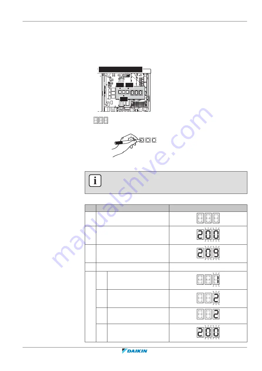
15.1.3 Recovery mode — In case of EPRA-DBW1* models (7-segments display)

Before recovering refrigerant, make sure the electronic expansion valves are open.
When power is ON, this has to be done by using the recovery mode.

Components

To activate/deactivate the recovery mode, you need the following components:

BS1 BS3

BS2

EPRA-DBW1*

7‑segments display

BS1~BS3

Push buttons. Operate the push buttons with an insulated stick (such as a closed
ballpoint pen) to avoid touching of live parts.

To activate the recovery mode

INFORMATION

If you get confused in the middle of the process, press BS1 to return to the default
situation.

Before recovering refrigerant, activate the recovery mode as follows:

#

Action

7-segments display

(a)

1

Start from the default situation.

2

Select mode 2.

Press and hold 

BS1

 for 5 seconds.

3

Select setting 9.

Press 

BS2

 9 times.

4

Select value 2.

a

Display the current value.

Press 

BS3

 once.

b

Change the value to 2.

Press 

BS2

 once.

c

Enter the value in the system.

Press 

BS3

 once.

d

Confirm.

Press 

BS3

 once.

Summary of Contents for ETSXB16E

Page 1: ...in Altherma 3 H HT ECH O EPRA14D V3 EPRA16D V3 EPRA18D V3 EPRA14D W1 EPRA16D W1 EPRA18D W1 ETSH16P30E ETSH16P50E ETSHB16P30E ETSHB16P50E ETSX16P30E ETSX16P50E ETSXB16P30E ETSXB16P50E A B C Z 1 2 3 9 h...

Page 2: ...3 Possible options for the indoor unit 29 6 Application guidelines 33 6 1 Overview Application guidelines 33 6 2 Setting up the space heating cooling system 34 6 2 1 Single room 35 6 2 2 Multiple room...

Page 3: ...8 2 2 Precautions when connecting the water piping 90 8 2 3 To connect the water piping 90 8 2 4 To connect a pressure vessel 95 8 2 5 To fill the heating system 95 8 2 6 To protect the water circuit...

Page 4: ...rview Commissioning 237 11 2 Precautions when commissioning 238 11 3 Checklist before commissioning 238 11 4 Checklist during commissioning 239 11 4 1 Minimum flow rate 239 11 4 2 Air purge function 2...

Page 5: ...15 1 1 To manually open the electronic expansion valves 266 15 1 2 Recovery mode In case of EPRA DAV3 and EPRA DAW1 models 7 LEDs display 267 15 1 3 Recovery mode In case of EPRA DBW1 models 7 segmen...

Page 6: ...r basic and advanced usage Format Digital files on https www daikin eu Use the search function to find your model Installation manual Outdoor unit Installation instructions Format Paper in the box of...

Page 7: ...the installation and configuration of heating systems To access Heating Solutions Navigator registration to the Stand By Me platform is required For more information see https professional standbyme d...

Page 8: ...t Before performing maintenance and service tasks read the service manual For more information see the installer and user reference guide The unit contains rotating parts Be careful when servicing or...

Page 9: ...o and know to install the electrical components of the system including information on how to prepare for an installation Configuration What to do and know to configure the system after it is installe...

Page 10: ...per installation or attachment of equipment or accessories could result in electrical shock short circuit leaks fire or other damage to the equipment ONLY use accessories optional equipment and spare...

Page 11: ...e unit Make sure the area is well ventilated Do NOT block any ventilation openings Make sure the unit is level Do NOT install the unit in the following places In potentially explosive atmospheres In p...

Page 12: ...use of oxygen going into the operating compressor NOTICE To avoid compressor breakdown do NOT charge more than the specified amount of refrigerant When the refrigerant system is to be opened refrigera...

Page 13: ...ation manual or installer reference guide of your application for more information NOTICE Make sure water quality complies with EU directive 2020 2184 2 1 5 Electrical DANGER RISK OF ELECTROCUTION Tur...

Page 14: ...ctor WARNING After finishing the electrical work confirm that each electrical component and terminal inside the electrical components box is connected securely Make sure all covers are closed before s...

Page 15: ...on the radio waves a distance of 1 meter may NOT be sufficient NOTICE ONLY applicable if the power supply is three phase and the compressor has an ON OFF starting method If there exists the possibili...

Page 16: ...llow the service space dimensions in this manual for correct installation of the unit Outdoor unit See 16 1 Service space Outdoor unit 4275 Indoor unit See 7 1 3 Installation site requirements of the...

Page 17: ...the indoor unit 484 WARNING Fixing method of the indoor unit MUST be in accordance with the instructions from this manual See 7 4 Mounting the indoor unit 484 Opening and closing the units see 7 2 Ope...

Page 18: ...ol systems since the presence may lead to the precipitation of certain components in the glycol s corrosion inhibitor Electrical installation see 9 Electrical installation 4103 DANGER RISK OF ELECTROC...

Page 19: ...he discharge grille and put the grille in safety position 482 WARNING The backup heater MUST have a dedicated power supply and MUST be protected by the safety devices required by the applicable legisl...

Page 20: ...the hot water tap never rise above a set maximum value This maximum allowable hot water temperature shall be selected according to the applicable legislation CAUTION Make sure that the disinfection f...

Page 21: ...ing device such as a timer or connected to a circuit that is regularly turned ON and OFF by the utility WARNING Air purging heat emitters or collectors Before you purge air from heat emitters or colle...

Page 22: ...the path along which you want to bring the unit to its final installation position In this chapter 4 1 Outdoor unit 22 4 1 1 To handle the outdoor unit 22 4 1 2 To unpack the outdoor unit 23 4 1 3 To...

Page 23: ...6P30 50E Daikin Altherma 3 H HT ECH O 4P679467 1C 2023 07 Manually After unpacking carry the unit using the slings attached to the unit See also 4 1 2 To unpack the outdoor unit 423 7 3 4 To install t...

Page 24: ...door unit h i a b d c f e g ENERG IJA Y IA IE ENERG IJA Y IA IE a O ring for drain socket b Drain socket c Shut off valve with integrated filter d Thermistor fixture for installations in areas with lo...

Page 25: ...OTICE Unpacking When you remove the top packaging accessories hold the box containing the discharge grille to prevent it from falling 4 2 Indoor unit 4 2 1 To unpack the indoor unit 4 2 2 To remove th...

Page 26: ...llation manual t Operation manual u Addendum software changelog v Addendum commercial warranty 4 2 3 To handle the indoor unit Use the handles at the back and at the front to carry the unit NOTICE The...

Page 27: ...unit 28 5 3 2 Possible options for the outdoor unit 29 5 3 3 Possible options for the indoor unit 29 5 1 Overview About the units and options This chapter contains information about Identifying the ou...

Page 28: ...Code Description E European model TS Floor standing hydro split unit with integrated pressureless storage tank H H Heating only X Heating cooling B Integrated heat exchanger for bivalent heat generato...

Page 29: ...g wired controls Multi zoning base unit 230 V EKWUFHTA1V3 Digital thermostat 230 V EKWCTRDI1V3 Analogue thermostat 230 V EKWCTRAN1V3 Actuator 230 V EKWCVATR1V3 For installation instructions see the in...

Page 30: ...to avoid direct sunlight to have an improved system behaviour For installation instructions see the installation manual of the remote outdoor sensor and the addendum book for optional equipment INFOR...

Page 31: ...ation instructions see the installation and operation manual of the Human Comfort Interface HCI as room thermostat and the addendum book for optional equipment Smart grid relay kit EKRELSG The install...

Page 32: ...and drain kit Recirculation kit 141554 By connecting a DHW pump instant hot water can be available at the tap To reduce heat losses while DHW pump is working you can install a recirculation kit For in...

Page 33: ...4 5 DHW pump for disinfection 57 6 5 Setting up the energy metering 57 6 5 1 Produced heat 58 6 5 2 Consumed energy 58 6 5 3 Normal kWh rate power supply 59 6 5 4 Preferential kWh rate power supply 6...

Page 34: ...tat ON OFF signal voltage free contact closed contact thermo ON open contact thermo OFF 6 2 Setting up the space heating cooling system The heat pump system supplies leaving water to heat emitters in...

Page 35: ...Setting Value Unit temperature control 2 9 Code C 07 2 Room thermostat Unit operation is decided based on the ambient temperature of the dedicated Human Comfort Interface Number of water temperature...

Page 36: ...t optional equipment EKRTR1 or EKRTRB Configuration Setting Value Unit temperature control 2 9 Code C 07 1 External room thermostat Unit operation is decided by the external thermostat Number of water...

Page 37: ...rs For more information see The installation manual of the heat pump convectors The installation manual of the heat pump convector options The addendum book for optional equipment The space heating co...

Page 38: ...e electrical wiring to the unit see 9 2 Connections to the outdoor unit 4108 9 3 Connections to the indoor unit 4115 The heat pump convectors are directly connected to the indoor unit A shut off valve...

Page 39: ...mp system Comfort The combination of the two heat emitter types provides The excellent heating comfort of the underfloor heating The excellent cooling comfort of the heat pump convectors 6 2 2 Multipl...

Page 40: ...connected to the indoor unit The room temperature of the main room is controlled by the dedicated Human Comfort Interface BRC1HHDA used as room thermostat A thermostatic valve is installed before the...

Page 41: ...e operation provide a minimum water flow as described in table To check the water volume and flow rate in 8 1 Preparing water piping 486 The user interface integrated in the indoor unit decides the sp...

Page 42: ...the heat pump convectors The installation manual of the heat pump convector options The addendum book for optional equipment The user interface integrated in the indoor unit decides the space operatio...

Page 43: ...shut off valve to prevent hot water supply when the room has no heating demand A shut off valve to prevent condensation on the floor during cooling operation of the rooms with heat pump convectors Fo...

Page 44: ...esign temperature in cooling Additional zone Zone with the highest design temperature in heating and the lowest design temperature in cooling CAUTION If there is more than one leaving water zone ALWAY...

Page 45: ...ystem with hydraulic separator for main zone B C a a f A E D b c g d e h 3 System with hydraulic separator for both zones For this system a direct pump is required for the additional zone B C a a f A...

Page 46: ...KMIKPOA based on the heating request of the room The room temperature is controlled by the dedicated Human Comfort Interface BRC1HHDA used as room thermostat Ensure water circulation is possible in ma...

Page 47: ...Code 7 02 1 Dual zone Main additional In case of heat pump convectors External room thermostat for the additional zone 3 A Code C 06 1 1 contact When the used external room thermostat or heat pump con...

Page 48: ...rt for each individual installation INFORMATION For systems without indirect auxiliary boiler connected to the storage tank it is mandatory to install an electric backup heater to ensure safe operatio...

Page 49: ...rmined automatically depending on the outdoor temperature During heating operation of the auxiliary boiler the auxiliary boiler operates to achieve the desired water temperature set via the auxiliary...

Page 50: ...air thermistor install the outdoor unit in the shadow so that it is NOT influenced or turned ON OFF by direct sunlight Frequent changeover may cause corrosion of the auxiliary boiler Contact the manuf...

Page 51: ...liary gas boiler must have a fixed setpoint 55 C or a weather dependent setpoint Tmin 0 30 25 20 15 10 5 0 5 20 30 40 50 60 10 Ta C Tmin C Ta Outdoor temperature Tmin Minimum weather dependent setpoin...

Page 52: ...on the indoor unit X12M 3 and X12M 4 See 9 3 10 To connect the changeover to external heat source 4130 Configuration Via the user interface configuration wizard Set the use of an indirect bivalent sy...

Page 53: ...adient of the solar piping MUST be guaranteed This is to allow the solar system to completely drain and thereby to avoid frost damages Configuration Via the user interface Select whether all other hea...

Page 54: ...user interface configuration wizard Set the backup heater voltage Set the capacity steps if applicable 6 4 Setting up the storage tank 6 4 1 System layout Integrated storage tank b a A A Domestic hot...

Page 55: ...46 C 245 l of mixed water at 40 C 55 C 425 l of mixed water at 40 C Energy saving tips If the DHW consumption differs from day to day you can program a weekly schedule with different desired storage...

Page 56: ...heat source see 6 3 Setting up bivalent heat sources 448 For more information about optimizing the energy consumption for producing domestic hot water see 10 Configuration 4142 6 4 4 DHW pump for inst...

Page 57: ...t during disinfection see 2 03 in the field settings table you can connect a DHW pump and heater element as shown above If applicable legislation requires disinfection of the water piping until the ta...

Page 58: ...energy Calculating Measuring INFORMATION You cannot combine calculating the consumed energy example for backup heater and measuring the consumed energy example for outdoor unit If you do so the energy...

Page 59: ...r model is 3V or 6V connected to a single phase grid Single phase 3V 6V 6V 1N 230 V Three phase outdoor unit Backup heater supplied from a three phase grid i e the backup heater model is 9W Three phas...

Page 60: ...number of pulses of each power meter See 6 5 4 Preferential kWh rate power supply 460 for an example with two power meters 6 5 4 Preferential kWh rate power supply General rule Power meter 1 Measures...

Page 61: ...he power consumption of the entire heat pump system sum of indoor unit and backup heater via 4 digital inputs Limitation of power in kW or current in A 3 6 6 4 BBR16 power limitation 464 Restriction O...

Page 62: ...5 Select continuous limitation mode Select the type of limitation power in kW or current in A Set the desired power limitation level 6 6 2 Power limitation activated by digital inputs Power limitation...

Page 63: ...ion control settings in 9 9 via the user interface for the description of all settings see Power consumption control 4215 Select limitation by digital inputs Select the type of limitation power in kW...

Page 64: ...ings BBR16 activation and BBR16 power limit After 2 weeks the unit freezes these settings Note This is different from the permanent power limitation which is always changeable Use the BBR16 power limi...

Page 65: ...sensor 9 B Outdoor ambient temperature In the outdoor unit the outdoor ambient temperature is measured Therefore the outdoor unit must be installed on a location At the north side of the house or at...

Page 66: ...To install the outdoor unit 78 7 3 5 To provide drainage 79 7 3 6 To install the discharge grille 80 7 3 7 To remove the discharge grille and put the grille in safety position 82 7 4 Mounting the ind...

Page 67: ...let Do NOT install the unit in the following places Sound sensitive areas e g near a bedroom so that the operation noise will cause no trouble Note If the sound is measured under actual installation c...

Page 68: ...refrigerant circuit R32 but you do NOT have to do any refrigerant field piping or refrigerant charging Mind the following requirements and precautions WARNING Do NOT pierce or burn refrigerant cycle...

Page 69: ...ct the unit If lateral snowfall is possible make sure that the heat exchanger coil is NOT affected by the snow If necessary install a snow cover or shed and a pedestal 7 1 3 Installation site requirem...

Page 70: ...must be level and smooth Do NOT install the unit in places such as In places where a mineral oil mist spray or vapour may be present in the atmosphere Plastic parts may deteriorate and fall off or cau...

Page 71: ...e unit DANGER RISK OF ELECTROCUTION Do NOT leave the unit unattended when the service cover is removed 7 2 2 To open the outdoor unit DANGER RISK OF ELECTROCUTION DANGER RISK OF BURNING SCALDING 1 1 2...

Page 72: ...rom both transportation stays a 2 Remove and discard the washers c and transportation stays a 3 Re install the nuts b of the compressor mounting bolt and tighten to 10 1 N m of torque 4 b a a a a a a...

Page 73: ...the transportation stay to fix it see 7 2 3 To remove the transportation stay 471 7 2 5 To close the outdoor unit NOTICE When closing the outdoor unit cover make sure that the tightening torque does N...

Page 74: ...r NOTICE Do NOT damage or remove the foam sealing of the switch box 3 Disconnect the ground connection from the top cover of the switch box 1 7 2 7 To lower the switch box of the indoor unit and remov...

Page 75: ...CH O 4P679467 1C 2023 07 2 2 1 3 Lower the switch box 1 4 If switch box is opened Disconnect the ground connection from the top cover of the switch box 5 If necessary remove the top cover This is nece...

Page 76: ...all the user interface panel NOTICE When closing the indoor unit make sure that the tightening torque does NOT exceed 4 1 N m 7 3 Mounting the outdoor unit 7 3 1 About mounting the outdoor unit When Y...

Page 77: ...nit will not cause any operating vibration or noise Fix the unit securely by means of foundation bolts in accordance with the foundation drawing NOTICE Level Make sure the unit is leveled in all direc...

Page 78: ...479 a 150 mm 4 M12 a Make sure not to cover the drain hole in the bottom plate of the unit 7 3 4 To install the outdoor unit CAUTION To avoid injury do NOT touch the air inlet or aluminium fins of the...

Page 79: ...e unit Avoid drain water flowing over the footpath so that it does NOT become slippery in case of ambient freezing temperatures If you install the unit on a frame install a waterproof plate within 150...

Page 80: ...now Use the drain plug with O ring and a hose for drainage 1 2 a b c c 3 d a Drain hole b O ring delivered as accessory c Drain plug delivered as accessory d Hose field supply NOTICE O ring Make sure...

Page 81: ...er screws 3 2 5 N m Install the upper part of the discharge grille NOTICE Vibrations Make sure the upper part of the discharge grille is attached seamlessly to the lower part to prevent vibrations 4 A...

Page 82: ...ut the grille in safety position WARNING Rotating fan Before powering ON or servicing the outdoor unit make sure that the discharge grille covers the fan as protection against a rotating fan See 7 3 6...

Page 83: ...A14 18D ETSH X B 16P30 50E Daikin Altherma 3 H HT ECH O 4P679467 1C 2023 07 4 3 Rotate the lower part of the discharge grille 4 Align the ball stud and hook on the grille with their counterparts on th...

Page 84: ...ions 410 7 1 Preparing the installation site 466 7 4 3 To install the indoor unit 1 Lift the indoor unit from the pallet and place it on the floor Also see 4 2 3 To handle the indoor unit 426 2 Connec...

Page 85: ...nsure the water can flow through the drain hose Ensure that the water level cannot mount above the overspill 6 Connect the drain pan hose to the drain pan connection and connect to an appropriate drai...

Page 86: ...to the piping can lead to excessive corrosion Connecting piping Legislation Make all piping connections in accordance with the applicable legislation and the instructions in the Installation chapter r...

Page 87: ...atible with water used in the system and with the materials used in the indoor unit Field supply components Water pressure and temperature Check that all components in the field piping can withstand t...

Page 88: ...s or non diffusion proof floor heating pipes it is necessary to install a magnetic filter dirt separator into the return flow of the system If the indoor unit is connected to a domestic cold water sup...

Page 89: ...inimum 20 litres the internal water volume of the outdoor unit NOT included INFORMATION In critical processes or in rooms with a high heat load extra water might be required NOTICE When circulation in...

Page 90: ...necting water piping 8 2 1 About connecting the water piping Before connecting the water piping Make sure the outdoor and indoor unit are mounted Typical workflow Connecting the water piping typically...

Page 91: ...the field piping to the outdoor unit water outlet NOTICE About the shut off valve with integrated filter delivered as accessory The installation of the valve at the water inlet is mandatory Mind the...

Page 92: ...e damaged if NOT handled correctly ONLY remove parts in the order and direction as indicated here do NOT use force do NOT use tools re install the thermal insulation in reverse order 3 Connect the shu...

Page 93: ...ue Thread size 1 25 30 N m To avoid damage apply the necessary countertorque with a suitable tool 1 2 6 Cut open the top cover If the space heating cooling or the domestic hot water pipes are directed...

Page 94: ...ctions as well as on the domestic cold water in and domestic hot water out connections These shut off valves are field supplied However make sure there is no valve between the pressure relief valve fi...

Page 95: ...installation piping tapping points etc connected to the tank is subjected to this high pressure To prevent this a pressure relief valve needs to be installed The overpressure prevention depends on the...

Page 96: ...g to the instructions see To purge the air out of the unit with the manual air vent valves 4241 3 Open the water tap 4 Open fill and drain valve and monitor the manometer 5 Fill the system with water...

Page 97: ...e protection valves Possible consequence Glycol leaking out of the freeze protection valves Freeze protection by glycol About freeze protection by glycol Adding glycol to the water lowers the freezing...

Page 98: ...om freezing NOTICE The required concentration might differ depending on the type of glycol ALWAYS compare the requirements from the table above with the specifications provided by the glycol manufactu...

Page 99: ...For example an automatic air purge b Protection for the field piping Install the freeze protection valves At all lowest points of the field piping In the coldest part of the field piping away from he...

Page 100: ...2 7 To fill the heat exchanger inside the storage tank Following heat exchanger have to be filled with water before the storage tank can be filled The domestic hot water heat exchanger NOTICE To fill...

Page 101: ...nection 2 Fill the storage tank until water spills from the spillover connection 3 Remove the hose a Drainback connection b Spillover connection c Hose with non return valve 1 2 With installed drainba...

Page 102: ...table as a minimum with 0 039 W mK Piping length m Minimum insulation thickness mm 20 19 20 30 32 30 40 40 40 50 50 For other cases the minimum insulation thickness can be determined using the Hydroni...

Page 103: ...ty meters 126 9 3 7 To connect the domestic hot water pump 127 9 3 8 To connect the alarm output 128 9 3 9 To connect the space cooling heating ON OFF output 129 9 3 10 To connect the changeover to ex...

Page 104: ...is equipped with an inverter A phase advancing capacitor will reduce performance and may cause accidents WARNING Rotating fan Before powering ON or servicing the outdoor unit make sure that the disch...

Page 105: ...al on the end of the wire Place the round crimp style terminal on the wire up to the covered part and fasten the terminal with the appropriate tool Use the following methods for installing wires Wire...

Page 106: ...ric service at competitive prices and are often authorised to bill clients at benefit rates E g time of use rates seasonal rates W rmepumpentarif in Germany and Austria This equipment allows for conne...

Page 107: ...5 580 1 50 0 0 2 b 3 During preferential kWh rate power supply activation power supply is NOT interrupted The outdoor unit is turned off by the control Remark The electricity company must always allow...

Page 108: ...o connect the electrical wiring to the outdoor unit 1 Open the switch box cover See 7 2 2 To open the outdoor unit 471 2 Strip insulation 20 mm from the wires a b a Strip wire end to this point b An e...

Page 109: ...mum running current Refer to name plate on unit L N PE b a L N Q1DI 1N 50 Hz 230 V AC F1B 1 3 2 4 I I BRN BLU YLW GRN b a L N a Power supply cable field supply b Field wiring F1B Overcurrent fuse fiel...

Page 110: ...ional Drain tube heater cable Make sure the heating element of the drain tube heater is completely inside the drain tube Route the cable through the frame Connect the wires to the terminal block and t...

Page 111: ...t X804A to X806A X806A X804A X805A INFORMATION Power saving function The power saving function is only applicable for V3 models For more information about the power saving function 9 F or overview fie...

Page 112: ...U YLW GRN a Power supply cable field supply b Field wiring F1B Overcurrent fuse field supply Recommended fuse 4 pole 16 A or 20 A fuse C curve Q1DI Earth leakage circuit breaker 30 mA field supply 2 I...

Page 113: ...ional Drain tube heater cable Make sure the heating element of the drain tube heater is completely inside the drain tube Route the cable through the frame Connect the wires to the terminal block and t...

Page 114: ...16P30 50E Daikin Altherma 3 H HT ECH O 4P679467 1C 2023 07 1 2 9 2 2 To reposition the air thermistor on the outdoor unit This procedure is only necessary in areas with low ambient temperatures Requir...

Page 115: ...4128 Space cooling heating operation control See 9 3 9 To connect the space cooling heating ON OFF output 4129 Changeover to external heat source control See 9 3 10 To connect the changeover to extern...

Page 116: ...mp convector options Addendum book for optional equipment Wires 0 75 mm Maximum running current 100 mA For the main zone 2 9 Control 2 A Ext thermostat type For the additional zone 3 A Ext thermostat...

Page 117: ...stat without multi zoning base unit Installation manual of the wired room thermostat Addendum book for optional equipment Wired room thermostat with multi zoning base unit Installation manual of the w...

Page 118: ...23 07 If the switch box is lowered in service position while the electrical installation is done additional cable length has to be taken into account adequately The cable routing in normal position is...

Page 119: ...ables are connected to one of the terminals Otherwise the cables could be too short X12M 9 3 2 To connect the main power supply 1 Open the following see 7 2 6 To open the indoor unit 473 1 User interf...

Page 120: ...Wh rate power supply Interconnection cable Wires 3 GND 1 5 mm Power supply indoor unit Wires 1N GND Maximum running current 6 3 A Preferential kWh rate power supply contact Wires 2 0 75 1 25 mm Maximu...

Page 121: ...ngs General information see 9 3 1 To connect the electrical wiring to the indoor unit 4117 9 3 3 To connect the backup heater power supply Backup heater type Power supply Wires EKECBU 3V 1N 230 V 2 GN...

Page 122: ...Electrical equipment complying with EN IEC 61000 3 12 European International Technical Standard setting the limits for harmonic currents produced by equipment connected to public low voltage systems...

Page 123: ...er reference guide 123 EPRA14 18D ETSH X B 16P30 50E Daikin Altherma 3 H HT ECH O 4P679467 1C 2023 07 Model power supply Connections to backup heater power supply 3V 3V 1N 230 V 1N 50 Hz 230 V AC SWB2...

Page 124: ...SWB2 Q1DI L1 L2 L3 N X6M 1 2 3 4 5 6 F1B 20A I I I F1B Overcurrent fuse field supply Recommended fuse tripping class C Q1DI Earth leakage circuit breaker field supply SWB Switch box X6M Terminal field...

Page 125: ...ATION Shut off valve usage example In case of one LWT zone and a combination of underfloor heating and heat pump convectors install a shut off valve before the underfloor heating to prevent condensati...

Page 126: ...r meter 0 75 mm Electricity meters 12 V DC pulse detection voltage supplied by PCB 9 A Energy metering INFORMATION In case of an electricity meter with transistor output check the polarity The positiv...

Page 127: ...ical wiring to the indoor unit 4117 9 3 7 To connect the domestic hot water pump Wires 2 GND 0 75 mm DHW pump output Maximum load 2 A inrush 230 V AC 1 A continuous 9 2 2 DHW pump 9 2 3 DHW pump sched...

Page 128: ...ee 9 3 1 To connect the electrical wiring to the indoor unit 4117 9 3 8 To connect the alarm output Wires 2 0 75 mm Maximum load 0 3 A 230 V AC Maximum load 1 A 5 V DC 9 D Alarm output 1 Open the foll...

Page 129: ...indoor unit 4117 9 3 9 To connect the space cooling heating ON OFF output INFORMATION Cooling is only applicable in case of reversible models Wires 2 0 75 mm Maximum load 0 3 A 230 V AC Maximum load 1...

Page 130: ...over to external heat source INFORMATION Bivalent is only possible in case of 1 leaving water temperature zone with room thermostat control OR external room thermostat control Wires 2 0 75 mm Maximum...

Page 131: ...o connect the electrical wiring to the indoor unit 4117 9 3 11 To connect the power consumption digital inputs Wires 2 per input signal 0 75 mm Power limitation digital inputs 12 V DC 12 mA detection...

Page 132: ...3 H HT ECH O 4P679467 1C 2023 07 1 2 3 3 Connect the power consumption digital inputs cable to the appropriate terminals as shown in the illustration below 4 Fix the cable with cable ties to the cable...

Page 133: ...able load of 15 V DC 10 mA 9 8 1 3 Benefit kWh power supply Safety thermostat 1 Open the following see 7 2 6 To open the indoor unit 473 1 User interface panel 1 3 4 2 2 Switch box 3 Switch box cover...

Page 134: ...hermostat after it is installed Without configuration the unit will ignore the safety thermostat contact 9 3 13 To connect a Smart Grid This topic describes 2 possible ways to connect the indoor unit...

Page 135: ...of low voltage contacts is as follows 8 7 S11S 6 5 S S 10 4 3 X 5M 1 S S 4 10 9 a 2 1 a Jumper factory mounted If you also connect a safety thermostat Q4L replace the jumper with the safety thermostat...

Page 136: ...4 K1A L N L N STEP 3 a b c d e f STEP 1 STEP 2 A1 A2 25 24 25 23 X1 M 2 K2A A1 A2 2 1 STEP 1 Smart Grid relay kit installation STEP 2 Low voltage connections STEP 3 High voltage connections 1 High vol...

Page 137: ...l installation Installer reference guide 137 EPRA14 18D ETSH X B 16P30 50E Daikin Altherma 3 H HT ECH O 4P679467 1C 2023 07 X M 10 K1A X10M K2A 3 Install the components of the Smart Grid relay kit as...

Page 138: ...ETSH X B 16P30 50E Daikin Altherma 3 H HT ECH O 4P679467 1C 2023 07 K1A K2A X15M X12M X 5M M X 1 12 3 4 5 6 X15M 3 X12M 23 X12M 24 X12M 25 X12M 25 X15M 5 X15M 4 X15M 6 23 24 25 4 Connect the low volt...

Page 139: ...2023 07 6 Fix the cable with cable ties to the cable tie mountings General information see 9 3 1 To connect the electrical wiring to the indoor unit 4117 9 3 14 To connect the WLAN cartridge delivere...

Page 140: ...To open the indoor unit 473 1 User interface panel 1 3 4 2 2 Switch box 3 Switch box cover 4 Top cover 2 Connect the solar input cable as shown in the illustration below 3 Fix the cable with cable ti...

Page 141: ...H O 4P679467 1C 2023 07 1 User interface panel 1 3 4 2 2 Switch box 3 Switch box cover 4 Top cover 2 Connect the DHW signal cable as shown in the illustration below 3 Fix the cable with cable ties to...

Page 142: ...rves 160 10 5 Settings menu 162 10 5 1 Malfunctioning 162 10 5 2 Room 162 10 5 3 Main zone 166 10 5 4 Additional zone 177 10 5 5 Space heating cooling 181 10 5 6 Tank 190 10 5 7 User settings 196 10 5...

Page 143: ...methods However NOT all settings are accessible via both methods If so the corresponding table columns in this chapter are set to N A not applicable Method Column in tables Accessing settings via the...

Page 144: ...s can be configured via the menu structure If for any reason it is required to change a setting using the overview settings then the overview settings can be accessed as follows 1 Set the user permiss...

Page 145: ...ded when updating the hydro software and EEPROM Prerequisite The EKPCCAB4 kit is required 1 Connect the USB connector of the cable to your PC 2 Connect the plug of the cable to X10A on A1P of the swit...

Page 146: ...cy 9 5 Number of zones 4 4 10 5 5 Space heating cooling 4181 Glycol Filled system overview field setting E 0D 10 5 9 Installer settings 4203 Solar 9 2 4 10 5 9 Installer settings 4203 Backup heater Vo...

Page 147: ...g WD curve 3 5 if applicable Cooling WD curve 3 6 if applicable Schedule 3 1 WD curve type 3 C read only Tank Heat up mode 5 6 10 5 6 Tank 4190 Hysteresis 5 9 10 3 Possible screens 10 3 1 Possible scr...

Page 148: ...the list of the main menu Go to the main menu screen Enable disable breadcrumbs Item Description a Domestic hot water a1 Domestic hot water a2 55 Measured tank temperature a b Disinfection Powerful Di...

Page 149: ...room thermostat installed or set Unit operation is decided based on the leaving water temperature regardless of the actual room temperature and or heating demand of the room i2 Installed heat emitter...

Page 150: ...Enter the submenu Enable disable breadcrumbs Submenu Description 0 or Malfunctioning Restriction Only displayed if a malfunction occurs See 14 4 1 To display the help text in case of a malfunction 426...

Page 151: ...he installer Perform tests and maintenance B User profile Change the active user profile C Operation Turn heating cooling functionality and domestic hot water preparation on or off D Wireless gateway...

Page 152: ...ption Minimum temperature limit a1 Fixed by the unit a2 Restricted by the installer Maximum temperature limit b1 Fixed by the unit b2 Restricted by the installer Current temperature c Measured by the...

Page 153: ...if room thermostat control is active If leaving water temperature control is active you can program the main zone schedule instead 1 Go to the schedule 2 optional Clear the content of the whole week s...

Page 154: ...efined 1 2 Select Edit Delete Edit Copy 3 Use the left dial to select an entry and edit the entry with the right dial You can program up to 6 actions each day On the bar a high temperature has a darke...

Page 155: ...defined 1 2 Select Copy Delete Edit Copy Result Next to the copied day C is displayed 3 Select Tuesday Mon Sat Wed Fri Thu Tue Sun User defined 1 C 4 Select Paste Delete Edit Copy Paste Result Mon Sat...

Page 156: ...fined 1 C To rename the schedule 1 Select the name of the current schedule Mon Sat Wed Fri Thu Tue Sun User defined 1 2 Select Rename Delete Rename Select 3 optional To delete the current schedule nam...

Page 157: ...o be able to compensate for differences in temperature the unit relies on its weather dependent curve This curve defines how much the temperature of the tank or leaving water must be at different outd...

Page 158: ...ges and proceed 10 4 3 Slope offset curve Slope and offset Define the weather dependent curve by its slope and offset Change the slope to differently increase or decrease the temperature of the leavin...

Page 159: ...ure at X1 is unequally higher than the preferred temperature at X2 When offset is changed the new preferred temperature at X1 is equally higher as the preferred temperature at X2 c Slope d Offset e Se...

Page 160: ...mode WD heating fixed cooling OR Weather dependent Main zone Cooling 2 4 Main zone Setpoint mode Weather dependent Additional zone Heating 3 4 Additional zone Setpoint mode WD heating fixed cooling O...

Page 161: ...ximum or minimum setpoint is reached the curve flattens out To fine tune the weather dependent curve slope offset curve The following table describes how to fine tune the weather dependent curve of a...

Page 162: ...Room Operation User profile Main zone 0 Malfunctioning 10 5 2 Room Overview The following items are listed in the submenu 1 Room Main zone Malfunctioning Operation Additional zone 1 Room Setpoint scr...

Page 163: ...9 Control External room thermostat and C 2 Space heating cooling Off or if 2 9 Control Leaving water In the above cases Antifrost will heat the space heating water to a reduced setpoint when the outdo...

Page 164: ...e Heating The unit will supply leaving water to the heat emitters to heat up the room according to normal logic Space heating cooling On and Operation mode Cooling There is no room frost protection Ex...

Page 165: ...ll supply leaving water to the heat emitters to heat up the room again Code Description 1 4 1 2 06 Activation 0 No Antifrost functionality is OFF 1 Yes Antifrost functionality is on 1 4 2 2 05 Room se...

Page 166: ...an Comfort Interface BRC1HHDA used as room thermostat Offset on the actual room temperature measured by the Human Comfort Interface 5 C 5 C step 0 5 C 1 7 2 09 Room sensor offset external room sensor...

Page 167: ...creen 2 Main zone See 10 3 5 Setpoint screen 4151 Schedule Indicate if the temperature of the leaving water is defined according to a schedule or not Influence of the LWT setpoint mode 2 4 is as follo...

Page 168: ...re for heating does NOT depend on the outdoor ambient temperature for cooling In Weather dependent mode the desired leaving water temperature depends on the outdoor ambient temperature Code Descriptio...

Page 169: ...ain zone Ta Outdoor temperature 1 00 Low outdoor ambient temperature 40 C 5 C 1 01 High outdoor ambient temperature 10 C 25 C 1 02 Desired leaving water temperature when the outdoor temperature equals...

Page 170: ...e higher than 1 09 as for low outdoor temperatures less cold water is required 1 09 Desired leaving water temperature when the outdoor temperature equals or rises above the high ambient temperature 9...

Page 171: ...hat in heating the zone with the lowest water temperature is configured as the main zone and the zone with the highest water temperature is configured as the additional zone NOTICE If there are 2 zone...

Page 172: ...and selection of the heat emitters The desired leaving water temperature is the result of several settings preset values shift values weather dependent curves modulation As a result too high or too lo...

Page 173: ...hermostat is used the external room thermostat will control the room frost protection However the room frost protection is only possible if C 2 Space heating cooling On Code Description 2 A C 05 Exter...

Page 174: ...NFORMATION In heating the target delta T will only be achieved after some operation time when the setpoint is being reached because of the big difference between leaving water temperature setpoint and...

Page 175: ...r noise level higher comfort and higher efficiency water temperatures as low as possible to match the desired temperature higher efficiency If Modulation is disabled set the desired leaving water temp...

Page 176: ...ng valve station ONLY when there is demand Code Description 2 D 1 F 0B The shut off valve 0 No is NOT influenced by heating or cooling demand 1 Yes closes when there is NO heating or cooling demand IN...

Page 177: ...screen Control the leaving water temperature for the additional zone via setpoint screen 3 Additional zone See 10 3 5 Setpoint screen 4151 Schedule Indicates if the desired leaving water temperature i...

Page 178: ...o the figure below 0 00 0 01 Ta Tt 0 03 0 02 Tt Target leaving water temperature additional zone Ta Outdoor temperature 0 03 Low outdoor ambient temperature 40 C 5 C 0 02 High outdoor ambient temperat...

Page 179: ...temperature 25 C 43 C 0 05 Desired leaving water temperature when the outdoor temperature equals or drops below the low ambient temperature 9 07 C 9 08 C Note This value should be higher than 0 04 as...

Page 180: ...the highest leaving water temperature in heating operation and the lowest leaving water temperature in cooling operation 3 8 1 9 05 Heating minimum 15 C 37 C 3 8 2 9 06 Heating maximum 2 0D 2 emitter...

Page 181: ...or E models If 2 0D 2 this is fixed to 10 C Else 3 C 10 C For E7 models If 2 0D 2 10 C 12 C Else 3 C 12 C 3 B 2 1 0E Delta T cooling A minimum temperature difference is required for the good operation...

Page 182: ...l is installed 1 Go to 4 Space heating cooling 2 Check if 4 1 Operation mode is listed and editable If so a heating cooling heat pump model is installed To tell the system which space operation to use...

Page 183: ...For each month select an option Reversible Not restricted Heating only Restricted Cooling only Restricted 4 Confirm the changes Example Changeover restrictions When Restriction During cold season Exam...

Page 184: ...d heating temperature Example A unit is configured as following Desired room temperature in heating mode 22 C Desired room temperature in cooling mode 24 C Hysteresis value 1 C Offset 4 C Changeover f...

Page 185: ...to 2 water temperature zones During configuration the number of water zones must be set INFORMATION Mixing station If your system layout contains 2 LWT zones you need to install a mixing station in f...

Page 186: ...ure emitter underfloor heating To avoid this Install an aquastat thermostatic valve to avoid too high temperatures towards a low temperature emitter Make sure you set the emitter types for the main zo...

Page 187: ...e is ONLY available in leaving water temperature control a b d e f c g b c a Space heating cooling control b Off c On d LWT temperature e Actual f Desired g Pump operation 4 5 F 0D 2 Request Pump oper...

Page 188: ...0D Restriction Only displayed when the bizone kit EKMIKPOA or EKMIKPHA is installed Pump limitation Additional zone Possible values see below Possible values Value Description 0 No limitation 1 4 Gene...

Page 189: ...he value set by the Space heating off temperature 4 02 or if the outdoor temperature drops below the value set by the Space cooling off temperature F 01 When the pump operation is enabled the pump ope...

Page 190: ...und 0 C 0 No 1 increase 2 C span 4 C 2 increase 4 C span 4 C 3 increase 2 C span 8 C 4 increase 4 C span 8 C Overshoot Restriction This function is only applicable in heating mode This function define...

Page 191: ...ely start heating up the water to the preset value Tank temperature setpoint However if no additional bivalent heat generator except the electrical backup heater is installed this consumes extra energ...

Page 192: ...always kept at the setpoint selected in the tank setpoint screen 3 Scheduled reheat The storage tank temperature varies according to the tank temperature schedule See the operation manual for more det...

Page 193: ...rupted by possible domestic hot water demand NOTICE Disinfection mode Even if you turn OFF tank heating operation C 3 Operation Tank disinfection mode will remain active However if you turn it OFF whi...

Page 194: ...is setting to limit the temperature at the hot water taps The maximum temperature is NOT applicable during disinfection function See disinfection function Hysteresis heat pump ON hysteresis Applicable...

Page 195: ...igh ambient temperature 35 C 6 0E C Margin In domestic hot water operation the following hysteresis value can be set for the heat pump operation Code Description 5 D 6 01 The temperature difference de...

Page 196: ...HW Domestic hot water temperature TU User setpoint temperature as set on the user interface t Time INFORMATION The maximum heat pump temperature depends on the ambient temperature For more information...

Page 197: ...from your normal schedules without having to change them While holiday mode is active space heating cooling operation and domestic hot water operation will be turned off Room frost protection and disi...

Page 198: ...mode schedule INFORMATION If the outdoor temperature is below zero we recommend to NOT use the most quiet level To check if quiet mode is active If is displayed on the home screen quiet mode is activ...

Page 199: ...Low 7 6 N A Gas price INFORMATION Electricity price can only be set when bivalent is ON 9 C 1 or C 02 These values can only be set in menu structure 7 5 1 7 5 2 and 7 5 3 Do NOT use overview settings...

Page 200: ...nt will be optimized NOTICE Make sure to modify the setting of the energy prices at the end of the incentive period To set the gas price in case of an incentive per kWh renewable energy Calculate the...

Page 201: ...ur energy consumption You can read out electricity input and produced heat divided into space heating space cooling and storage tank heating Additionally the storage tank heat provided e g by a solar...

Page 202: ...9 Item Description a Energy sources a1 Heat pump compressor is operating a2 Solar energy is available a3 Backup heater is activated a4 Boiler is activated b Actuator status b1 Pump is running b2 Heat...

Page 203: ...utside and leaving water temperature if applicable 8 5 Actuators Status mode of each actuator Example Domestic hot water pump ON OFF 8 6 Operation modes Current operation mode Example Defrost oil retu...

Page 204: ...st 9 I Overview field settings 9 N Export MMI settings 9 O Intelligent tank management 9 P Bizone kit Configuration wizard After first power ON of the system the user interface will guide you using th...

Page 205: ...le to determine when to turn on and off the pump When turned on the pump runs and makes sure hot water is instantly available at the tap To save energy only turn on the pump during periods of the day...

Page 206: ...of the second step in emergency Code Description 9 3 3 4 0A 0 Relay 1 1 Relay 1 Relay 1 2 2 Relay 1 Relay 2 3 Relay 1 Relay 2 Emergency Relay 1 2 INFORMATION Settings 9 3 3 and 9 3 5 are linked Changi...

Page 207: ...on Maximum capacity Code Description 9 3 9 4 07 Maximum capacity that should be delivered by the backup heater Range 1 kW 3 kW Step 1 kW Equilibrium Code Description 9 3 6 5 00 Equilibrium Deactivate...

Page 208: ...nteraction When Emergency is set to Automatic and a heat pump failure occurs the backup heater or boiler automatically takes over the domestic hot water production and space heating When Emergency is...

Page 209: ...to the tank via bivalent coil or via drain back connection the boiler and NOT the backup heater operates as emergency heater independent of the boiler capacity For small capacity boilers this may lead...

Page 210: ...ower than setting 5 03 the domestic hot water will not be heated with the backup heater If an auxiliary boiler is connected to the tank At ambient temperatures below 5 03 only the boiler is used for d...

Page 211: ...hot water operation Domestic hot water heating stops even when the target domestic hot water temperature is NOT reached The actual maximum running time also depends on setting 8 04 When Control Room...

Page 212: ...oes not have a booster heater Only set D 00 to the values in the table below D 00 Backup heater Compressor 0 Forced OFF Forced OFF 2 Allowed Smart Grid operation modes The 2 incoming Smart Grid contac...

Page 213: ...uffering with electrical heater is NOT possible in Forced on and Recommended on operation modes Code Description 9 8 2 D 00 Restriction Only applicable if 9 8 4 is NOT set to Smart Grid Allow heater W...

Page 214: ...art function 2 Closed The outdoor unit is connected to a preferential kWh rate power supply When the preferential kWh rate signal is sent by the electricity company the contact will close and the unit...

Page 215: ...available the following happens The pulse meter measures the power produced by the photovoltaic panels The unit limits its power consumption during the Smart Grid s Recommended ON mode to only use th...

Page 216: ...ase of full time current limitation mode 0 A 50 A Limits when 9 9 1 Inputs and 9 9 2 Amp Code Description 9 9 4 5 05 Limit 1 0 A 50 A 9 9 5 5 06 Limit 2 0 A 50 A 9 9 6 5 07 Limit 3 0 A 50 A 9 9 7 5 08...

Page 217: ...booster heater will be limited first before the backup heater is limited Note In case power consumption control is DISABLED for all models the setting 4 01 defines whether backup heater and booster he...

Page 218: ...ers configure the settings as described below Select the pulse frequency output of each power meter in accordance with the power meter specifications It is possible to connect up to 2 power meters wit...

Page 219: ...rk This value has only meaning in room thermostat control Ext amb sensor offset ONLY applicable in case an external outdoor ambient sensor is connected and configured You can calibrate the external ou...

Page 220: ...e heat generated by the auxiliary boiler should be used for domestic hot water heating only 3 Indirect DHW SH Set this value in case that the auxiliary boiler is connected to the storage tank and the...

Page 221: ...ration if applicable and the auxiliary boiler is based on the following settings C 03 and C 04 Electricity and gas prices 7 5 1 7 5 2 7 5 3 and 7 6 or PE factor 7 03 F 02 only for C 02 2 3 C 03 C 04 T...

Page 222: ...value of C 03 For DHW heating switch over The heat pump system calculates a value Tlim based on outdoor temperature and COP as defined above When storage tank temperature reaches Tlim the boiler is se...

Page 223: ...alarm output will be powered when an alarm occurs By setting this value a distinction is made between the detection of an alarm and the detection of a power failure 1 Normal The alarm output will NOT...

Page 224: ...ction setting E 08 needs to be enabled on the user interface Code Description 9 F E 08 Power saving function for outdoor unit 0 No 1 Yes Disable protections INFORMATION Protective functions Installer...

Page 225: ...to change a setting using the overview settings then the overview settings can be accessed in the field settings overview 9 I See To modify an overview setting 4144 Export MMI settings About exporting...

Page 226: ...e switch between space heating by heat pump while boiler is preheating the tank and space heating by tank heating support while boiler may or may not operate This applies only when tank energy is allo...

Page 227: ...operation HPSH Space heating by heat pump operation Ttank Storage tank temperature TankSH Space heating by tank heating support Tset In this example Tank setpoint may differ depending on space heatin...

Page 228: ...d Enabling the function for a too small boiler may lead to undesirable and potentially damaging on off switching behavior of the heat pump Continuous heating The continuous heating function allows to...

Page 229: ...d off 1 No Heat pump and boiler can operate also while solar energy is provided Bizone kit Additionally to the settings listed below make sure to also set 7 02 1 i e 4 4 Number of zones Dual zone when...

Page 230: ...separator with direct pump d c b a a Indoor unit b Mixing station c Hydraulic separator d Direct pump Additional zone pump fixed PWM The speed of the additional zone pump can be fixed with this settin...

Page 231: ...case a bizone kit is installed antiblockage of kit pump s and kit mixing valve Code Description 9 I 3 0D In case a bizone kit is installed antiblockage of kit pump s and kit mixing valve 0 disabled 1...

Page 232: ...ately enable or disable functionalities of the unit Code Description C 2 N A Space heating cooling 0 Off 1 On C 3 N A Tank 0 Off 1 On 10 5 13 WLAN INFORMATION Restriction WLAN settings are only visibl...

Page 233: ...ttp www onlinecontroller daikineurope com Configuration To configure the ONECTA app follow the in app instructions While doing this the following actions and information are needed on the user interfa...

Page 234: ...3 07 Home network connection Read out the status of the connection to the home network Code Description D 5 N A Home network connection Disconnected from WLAN_SSID Connected to WLAN_SSID Cloud connect...

Page 235: ...utes Year Month Day Daylight savings time Format 7 3 Holiday Activation From Till 7 5 Electricity price High Medium Low Schedule 5 Tank Powerful operation Schedule 1 9 Room comfort setpoint Heating co...

Page 236: ...rt Grid operation mode Allow electrical heaters Limit setting kW Enable room buffering Allow heater Allow pump 9 9 Power consumption control Power consumption control Type Limit Limit 1 Limit 2 Limit...

Page 237: ...The unit automatically runs these functions when necessary During installation or service this behaviour is undesired Therefore the protective functions can be disabled At first power on The protectiv...

Page 238: ...check the items listed below 2 Close the unit 3 Power up the unit You read the complete installation instructions as described in the installer reference guide The indoor unit is properly mounted Che...

Page 239: ...ing backup heater defrost operation is guaranteed in all conditions See To check the water volume and flow rate in 8 1 Preparing water piping 486 To perform an air purge To perform a test run To perfo...

Page 240: ...tic The unit automatically changes the pump speed and fixes the two mixing valves tank and bypass valve at middle position Typical workflow Purging the air from the system should consist of 1 Purging...

Page 241: ...t step 1 and 2 for valve b To perform a manual air purge Conditions Make sure all operation is disabled Go to C Operation and turn off Space heating cooling and Tank operation 1 Set the user permissio...

Page 242: ...done 6 To stop the air purge manually 1 In the menu go to Stop air purge 2 Select OK to confirm 11 4 3 Operation test run Purpose Perform test runs on the unit and monitor the leaving water and tank t...

Page 243: ...start To perform an actuator test run Conditions Make sure all operation is disabled Go to C Operation and turn off Space heating cooling and Tank operation 1 Set the user permission level to Installe...

Page 244: ...for the maximum allowed water temperature to avoid cracking the screed programming the underfloor heating screed dryout schedule according to the initial heating instructions of the screed manufactur...

Page 245: ...g The underfloor heating screed dryout function is active even if the user does NOT confirm emergency operation During underfloor heating screed dryout pump speed limitation 9 0D is NOT applicable NOT...

Page 246: ...red leaving water temperature 2 Press the left dial to open the menu structure and to 1 View the status of sensors and actuators 2 Adjust the current program To stop an underfloor heating UFH screed d...

Page 247: ...ctric backup heater to ensure safe operation for all conditions Drain back models For drain back models a backup heater EKECBUA must always be installed For drain back models the factory setting of fi...

Page 248: ...ting table in the operation manual with the actual settings Make sure that the user has the printed documentation and ask him her to keep it for future reference Inform the user that he can find the c...

Page 249: ...once a year However applicable legislation might require shorter maintenance intervals In this chapter 13 1 Overview Maintenance and service 249 13 2 Maintenance safety precautions 249 13 3 Yearly mai...

Page 250: ...can lead to too low pressure or too high pressure leading to worse performance Water filter Close the valve Clean and rinse the water filter NOTICE Handle the filter with care To prevent damage to the...

Page 251: ...e flush the system It is recommended to do this maintenance more frequently Switch box Carry out a thorough visual inspection of the switch box and look for obvious defects such as loose connections o...

Page 252: ...13 Maintenance and service Installer reference guide 252 EPRA14 18D ETSH X B 16P30 50E Daikin Altherma 3 H HT ECH O 4P679467 1C 2023 07...

Page 253: ...ning 256 14 3 5 Symptom The pump is blocked 257 14 3 6 Symptom The pump is making noise cavitation 257 14 3 7 Symptom The pressure relief valve opens 257 14 3 8 Symptom The water pressure relief valve...

Page 254: ...3 Solving problems based on symptoms 14 3 1 Symptom The unit is NOT heating or cooling as expected Possible causes Corrective action The temperature setting is NOT correct Check the temperature setti...

Page 255: ...Corrective action The compressor cannot start if the water temperature is too low The unit will use the backup heater to reach the minimum water temperature 12 C after which the compressor can start I...

Page 256: ...ing is not sufficient change the pump limitation settings 9 0D and 9 0E if applicable Various malfunctions Check if or is displayed on the home screen of the user interface See 14 4 1 To display the h...

Page 257: ...nd turn the rotor by hand 14 3 6 Symptom The pump is making noise cavitation Possible causes Corrective action There is air in the system Purge air manually see To perform a manual air purge 4241 or u...

Page 258: ...ar a clacking sound contact your dealer If the water keeps running out of the unit close both the water inlet and outlet shut off valves first and then contact your dealer 14 3 9 Symptom The space is...

Page 259: ...er settings Balancing Priority temperature 5 03 14 3 10 Symptom Tank disinfection function is NOT completed correctly AH error Possible causes Corrective action The disinfection function was interrupt...

Page 260: ...nctioning Result A short description of the error and the error code is displayed on the screen 2 Press in the error screen Result A long description of the error is displayed on the screen 14 4 2 To...

Page 261: ...ooling operation warning 8F 00 Abnormal increase outlet water temperature DHW 8H 00 Abnormal increase outlet water temperature 8H 01 Overheating undercooling mixed water circuit 8H 02 Overheating mixe...

Page 262: ...al temperature sensor problem H3 00 OU Malfunction of high pressure switch HPS H4 00 Malfunction of low pressure switch H5 00 Malfunction of compressor overload protection H6 00 OU Malfunction of posi...

Page 263: ...ect current P4 00 OU Malfunction of radiating fin temperature sensor PJ 00 Capacity setting mismatch U0 00 OU Shortage of refrigerant U1 00 Malfunction by reverse phase open phase U2 00 OU Defect of p...

Page 264: ...han the last expected large hot water tapping This start up can be set by installer settings disinfection function NOTICE When the minimum water flow is lower than described in the table below the uni...

Page 265: ...ureless solar system 271 15 2 2 To drain the storage tank with a connected pressureless solar system 273 15 1 To recover refrigerant When disposing of the outdoor unit you need to recover its refriger...

Page 266: ...els 7 segments display 4269 Result The unit returns the valves Y to their initial state To recover refrigerant when power is OFF 1 Manually open the valves Y see 15 1 1 To manually open the electronic...

Page 267: ...uch as a closed ballpoint pen to avoid touching of live parts To activate the recovery mode INFORMATION If you get confused in the middle of the process press BS1 to return to the default situation Be...

Page 268: ...mode as follows Action 7 LEDs display a H1P H2P H3P H4P H5P H6P H7P 1 Press and hold BS1 for 5 seconds 2 Press BS2 9 times 3 Press BS3 once 4 Press BS2 once 5 Press BS3 once 6 Press BS3 once 7 Press B...

Page 269: ...y BS1 BS3 Push buttons Operate the push buttons with an insulated stick such as a closed ballpoint pen to avoid touching of live parts To activate the recovery mode INFORMATION If you get confused in...

Page 270: ...re 7 segments display a 1 Start from the default situation 2 Select mode 2 Press and hold BS1 for 5 seconds 3 Select setting 9 Press BS2 9 times 4 Select value 1 a Display the current value Press BS3...

Page 271: ...fill and drain kit is available 1 Open the screw plug of the spillover connection 2 Unplug the spillover connector b 2 1 b a 3 a Spillover connector b Screw plug 3 Connect the loose end of the spillov...

Page 272: ...appropriate drain To drain the storage tank NOTICE Water immediately surges from the storage tank when the sealing plug of the drain connection is removed Make sure to adequately collect the spillage...

Page 273: ...drain the storage tank from the drain connection if an optional fill and drain kit is available described below Otherwise drain with a pump and a hose through the solar return connection 1 Switch the...

Page 274: ...ional Daikin website publicly accessible The full set of latest technical data is available on the Daikin Business Portal authentication required In this chapter 16 1 Service space Outdoor unit 275 16...

Page 275: ...A B C D E HB HU HD 150 H U The symbols can be interpreted as follows A C Right side and left side obstacles walls baffle plates B Suction side obstacle wall baffle plate D Discharge side obstacle wal...

Page 276: ...anger distributor d Pinched pipe R5T Air heat exchanger middle e Refrigerant filter R6T Refrigerant liquid f One way valve R7T Compressor shell g Economiser heat exchanger R8T Compressor port h Servic...

Page 277: ...1 b2 DHW Hot water OUT screw connection 1 c1 Water IN from outdoor unit screw connection 1 c2 Water OUT to outdoor unit screw connection 1 d1 Water IN from bivalent heat source screw connection 1 d2 W...

Page 278: ...ctronic component assembly Electronic component assembly Front side view Front side view Indoor Indoor OFF OFF ON ON Outdoor Outdoor Position of compressor terminal Position of compressor terminal Pos...

Page 279: ...ion table and the option manual for how to connect the wiring to X41A and X2M 6 In case of EPRA DAV3 and EPRA DAW1 models The factory setting of all switches is OFF do not change the setting of the se...

Page 280: ...ay L1R L3R A1P Reactor M1C Compressor motor M1F Fan motor PS A1P Switching power supply Q1DI Earth leakage circuit breaker 30 mA field supply R1 R5 A1P A2P Resistor R1T Thermistor outdoor air R2T Ther...

Page 281: ...rd main A2P Printed circuit board noise filter A3P Printed circuit board leakage current A4P Printed circuit board ACS A5P Printed circuit board inverter BS1 BS4 A1P Push button switch C1 C3 A2P Capac...

Page 282: ...gh pressure sensor S1PH S2PH High pressure switch S1PL Low pressure switch T1A Current transfo V1R V2R A2P IGBT power module V3R A2P Diode module X1M X2M Terminal strip Y1E Electronic expansion valve...

Page 283: ...or motor M1F Fan motor PS A1P Switching power supply Q1DI Earth leakage circuit breaker 30 mA field supply R2 R807 A1P Resistor R1T Thermistor outdoor air R2T Thermistor compressor discharge R3T Therm...

Page 284: ...1P IGBT power module X1M X2M Terminal strip Y1E Electronic expansion valve main black Y3E Electronic expansion valve injection blue Y1S Solenoid valve 4 way valve Y2S Solenoid valve low pressure bypas...

Page 285: ...ounted in switch box Wiring depending on model PCB Backup heater power supply Backup heater power supply 3V 1N 230 V 3 kW 3V 1N 230 V 3 kW 6V 1N 230 V 6 kW 6V 1N 230 V 6 kW 6WN 9WN 3N 400 V 6 9 kW 6WN...

Page 286: ...in PCB A2P On OFF thermostat PC power circuit A3P Heat pump convector A8P Demand PCB A11P MMI user interface of the indoor unit Main PCB A14P PCB of the dedicated Human Comfort Interface BRC1HHDA used...

Page 287: ...Translation of text on wiring diagram English Translation 1 Main power connection 1 Main power connection Outdoor unit Outdoor unit SWB1 Switch box 2 User interface 2 User interface Only for remote u...

Page 288: ...ter Gas meter Inrush Inrush current Max load Maximum load Normally closed Normally closed Normally open Normally open Note outputs can be taken from terminal positions X12M 17 L 18 N and X12M 17 L 11...

Page 289: ...heat pump convector 5 External On OFF thermostats and heat pump convector Additional LWT zone Additional leaving water temperature zone Main LWT zone Main leaving water temperature zone Only for exte...

Page 290: ...l Only for LV smartgrid 1 Smartgrid contact S10S FIELD SUPPLY X15M 5 6 signal Electricity meter pulse input 1 2 core X15M 9 10 Electricity meter pulse input 2 signal 2 core Smartgrid pulse meter 5 5 4...

Page 291: ...For E7 models D E F G A kPa B l min 0 20 40 60 80 100 120 C 0 5 10 15 20 25 30 35 40 45 50 A External static pressure in the space heating cooling circuit B Water flow rate through the unit in the sp...

Page 292: ...a Modelname b Manufacturing number c Manufacturing date d Empty weight e Total filled weight f Max operating pressure PMS heating circuit g Water volume storage tank h Max operating temperature Tmax...

Page 293: ...oduct or application explaining how to install configure and maintain it Operation manual Instruction manual specified for a certain product or application explaining how to operate it Maintenance ins...

Page 294: ...or units ETSH16P30E ETSH16P50E ETSHB16P30E ETSHB16P50E ETSX16P30E ETSX16P50E ETSXB16P30E ETSXB16P50E Notes 1 X 2 H 3 B 4 EKECBUA3V 5 EKECBUA6V 6 EKECBUA9W 7 BUH less 8 300L tank 9 E model E 10 E7 mode...

Page 295: ...step 1 C 20 C 2 6 1 07 R W 25 43 C step 1 C 35 C 2 6 1 08 R W 9 03 9 02 C step 1 C 22 C 2 6 1 09 R W 9 03 9 02 C step 1 C 2 0C 0 18 C 2 0C 1 7 C 2 0C 2 18 C Main zone Leaving water value for high amb...

Page 296: ...2 C 2 8 06 R W 0 10 C step 1 C 5 C Shut off valve 2 D 1 F 0B R W 0 No 1 Yes 2 D 2 F 0C R W 0 No 10 1 Yes 9 Main zone 2 E R W 0 2 points 1 Slope Offset Additional zone 3 4 0 Fixed 1 WD heating fixed co...

Page 297: ...step 1 C 5 C Additional zone 3 C R O 0 2 points 1 Slope Offset Space heating cooling Operation range 4 3 1 4 02 R W 14 35 C step 1 C 35 C 4 3 2 F 01 R W 10 35 C step 1 C 20 C Space heating cooling 4...

Page 298: ...3 hour step 1 hour 1 5 7 4 2 03 R W 60 C 60 C 5 7 5 2 04 R W 40 60 min step 5 min 40 min Tank 5 8 6 0E R W E 07 4 40 75 C step 1 C 65 C 5 9 6 00 R W 2 40 C step 1 C 8 C 5 A 6 08 R W 2 20 C step 1 C 10...

Page 299: ...uced DHW ON 3 Auto SH reduced DHW OFF 4 Auto SH normal DHW OFF 9 1 3 5 7 02 R W 0 Single zone 1 Dual zone 9 1 3 6 E 0D R W 0 No 1 Yes 9 1 3 7 6 02 R W 0 10kW step 0 2kW 0kW 9 1 3 8 C 02 R W 0 Off 1 Di...

Page 300: ...9 03 9 02 C step 1 C 2 0C 0 18 C 2 0C 1 7 C 2 0C 2 18 C Additional zone 9 1 8 1 2 0D R W 0 Underfloor heating 1 Fancoil unit 2 Radiator 9 1 8 3 R W 0 Fixed 1 WD heating fixed cooling 2 Weather depende...

Page 301: ...Circulation 4 Circulation and disinfection 9 2 4 D 07 R W 0 No 1 Yes DHW 2 Yes DHW SH Back up heater 9 3 1 E 03 R W 0 no heater 7 2 3V 4 3 6V 5 4 9W 6 9 3 2 5 0D R W 0 230V 1 4 5 7 2 400V 3 6 9 3 3 4...

Page 302: ...9 6 4 8 02 R W 0 10 hour step 0 5 hour 0 5 hour 9 6 5 8 00 R O 0 20 min step 1 min 1 min 9 6 6 8 01 R W 5 95 min step 5 min 30 min 9 6 7 8 04 R W 0 95 min step 5 min 95 min Installer settings 9 7 4 0...

Page 303: ...9 D 4 01 R W 0 None 1 Booster Heater 2 Backup Heater 9 9 F 7 07 R W 0 No 1 Yes Energy metering 9 A 1 D 08 R W 0 No 1 0 1 pulse kWh 2 1 pulse kWh 3 10 pulse kWh 4 100 pulse kWh 5 1000 pulse kWh 9 A 2...

Page 304: ...R W 25 43 C step 1 C 35 C 9 I 0 07 R W 10 25 C step 1 C 20 C 9 I 0 0B R W 35 6 0E C step 1 C 55 C 9 I 0 0C R W Min 45 6 0E 6 0E C step 1 C 60 C Leaving water value for low ambient temp for DHW WD curv...

Page 305: ...10 C step 1 C 5 C Leaving water value for high ambient temp for LWT main zone cooling WD curve What is the averaging time for the outdoor temp What is the desired delta T in heating for the main zone...

Page 306: ...Heater 9 I 4 02 R W 14 35 C step 1 C 35 C Which electric heater has priority Below which outdoor temperature is heating allowed What is the maximum desired room temperature in heating What is the mim...

Page 307: ...I 5 0C R W 0 20 kW step 0 5 kW 20 kW 9 I 5 0D R W 0 230V 1 4 5 7 2 400V 3 6 9 I 5 0E 1 9 I 6 00 R W 2 40 C step 1 C 8 C The temperature difference determining the heat pump ON temperature What is the...

Page 308: ...he desired eco storage temperature What is the desired reheat temperature BBR16 activation BBR16 settings are only visible when the language of the user interface is set to Swedish Minimum running tim...

Page 309: ...0E 6 9 I C 00 R W 0 Solar priority 1 Heat pump priority 9 I C 01 0 What is the mimimum desired LWT for main zone in cooling Leaving water temperature overshoot temperature Domestic heating water prior...

Page 310: ...h 2 1 pulse kWh 3 10 pulse kWh 4 100 pulse kWh 5 1000 pulse kWh 9 I D 09 R W 0 No 1 0 1 pulse kWh 2 1 pulse kWh 3 10 pulse kWh 4 100 pulse kWh 5 1000 pulse kWh 6 100 pulse kWh PV meter 7 1000 pulse kW...

Page 311: ...d 1 Allowed 9 I F 01 R W 10 35 C step 1 C 20 C 9 I F 02 3 9 I F 03 5 9 I F 04 0 9 I F 05 0 9 I F 06 R W 0 Disabled 1 Enabled 9 I F 07 R W 0 Enabled 1 Disabled 9 I F 08 R W 0 Disabled 1 Enabled 9 I F 0...

Page 312: ...mp 1 With hydraulic separator no direct pump 2 With hydraulic separator with direct pump 9 P 3 7 0A R W 20 95 step 5 95 9 P 4 7 0B R W 20 95 step 5 95 9 P 5 7 0C R W 20 300 sec step 5 sec 125 sec Add...

Page 313: ......

Page 314: ......

Page 315: ......

Page 316: ...4P679467 1C 2023 07 Copyright 2022 Daikin Verantwortung f r Energie und Umwelt...

Reviews: