


6
|
Application guidelines
Installer reference guide
38
EPRA14~18D + ET23E
Daikin Altherma 3 H HT F
4P644739-1A – 2022.03
Setup
▪
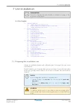
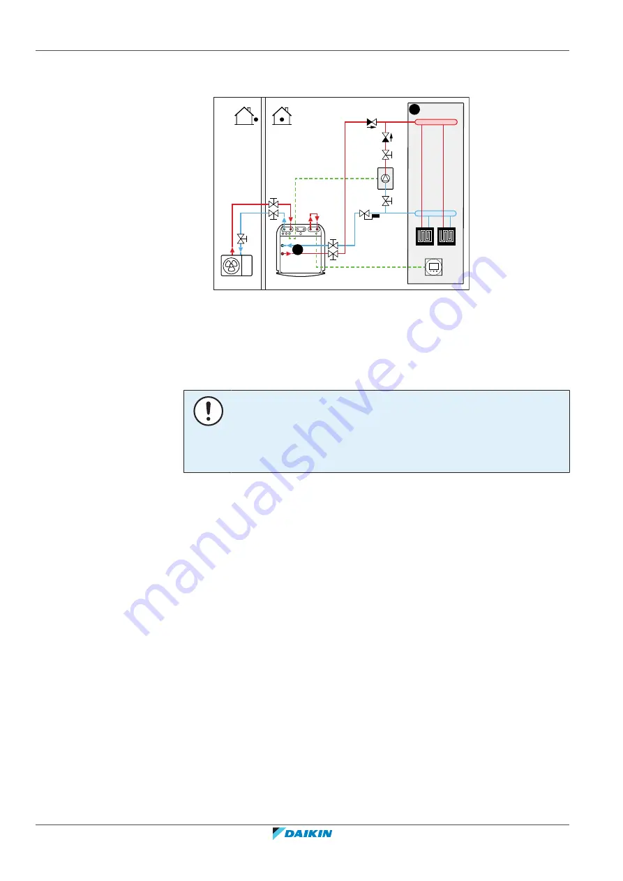
Integrate the auxiliary boiler as follows:
B
a
b
b
c
d
c
e
f
A
A
Main leaving water temperature zone
B
One single room
a
Dedicated Human Comfort Interface (BRC1HHDA used as room thermostat)
b
Non-return valve (field supply)
c
Shut-off valve (field supply)
d
Auxiliary boiler (field supply)
e
Aquastat valve (field supply)
f
Bypass (field supply)
NOTICE
▪
Make sure the auxiliary boiler and its integration in the system complies with
applicable legislation.
▪
Daikin is NOT responsible for incorrect or unsafe situations in the auxiliary boiler
system.
▪
Make sure the return water to the heat pump does NOT exceed 70°C. To do so:
-
Set the desired water temperature via the auxiliary boiler controller to
maximum 70°C.
-
Install an aquastat valve in the return water flow of the heat pump. Set the
aquastat valve to close above 70°C and to open below 70°C.
▪
Install non-return valves.
▪
An expansion vessel is already pre-mounted in the indoor unit. But for bivalent
operation, also make sure that there is an expansion vessel in the auxiliary boiler
loop. Otherwise when bivalent operation is running and if the Aquastat valve
would close, there would be no expansion vessel in the water circuit anymore.
▪
Install the digital I/O PCB (option EKRP1HBAA).
▪
Connect X1 and X2 (changeover to external heat source) on the digital I/O PCB to
the auxiliary boiler. See
"9.3.8 To connect the changeover to external heat
113].
▪
To setup the heat emitters, see
"6.2 Setting up the space heating/cooling
34].
Configuration
Via the user interface (configuration wizard):
▪
Set the use of a bivalent system as external heat source.
▪
Set the bivalent temperature and hysteresis.
Summary of Contents for ETVZ16E6V7
Page 281: ......
Page 282: ......
Page 283: ......
Page 284: ...4P644739 1A 2022 03 Copyright 2021 Daikin Verantwortung f r Energie und Umwelt...


