Checking the Inputs and Outputs
ESIE98–06A
3–14
Part 3 – Troubleshooting
3
1
3
4
5
3.2
Checking the Temperature Sensors
Introduction
If the cause of the problem is related to the temperature sensors, then the sensors should be checked
prior to changing the PCB or an output device.
Types of sensors
There are two types of temperature sensors:
■
sensors connected to the controller PCB: R3T/ R4T/ R5T/R6T
■
sensors connected to the defrost PCB: R11T/ R12T/ R21T/ R22T/ R31T/ R32T
How to check
To check the temperature sensors, proceed as follows:
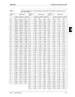
Table 1
In table 1 you will find the temperature-resistance values of the controller sensors R3T, R4T R5T and
R6T (see next page).
Table 2
In table 2 you will find the temperature-resistance values of the defrost sensors R11T, R12T, R21T,
R22T, R31T and R32T(see page 3-16).
Step
Action
1
Disconnect the sensor from the PCB.
2
Measure the temperature and the resistor value.
3
Check if the measured values correspond with the values in the appropriate table.
Summary of Contents for EUWA/Y5-30HB/C(Z)
Page 2: ......
Page 8: ...Introduction ESIE98 06A vi 3 1 4 5...
Page 10: ...ESIE98 06A 1 2 Part 1 System Outline 3 1 1 4 5...
Page 28: ...General Outline ESIE98 06A 1 20 Part 1 System Outline 3 1 1 4 5...
Page 36: ...Piping Layout ESIE98 06A 1 28 Part 1 System Outline 3 1 1 4 5...
Page 52: ...ESIE98 06A Wiring Layout Part 1 System Outline 1 44...
Page 58: ...ESIE98 06A 2 2 Part 2 Functional Description 3 1 2 4 5...
Page 100: ...ESIE98 06A 3 2 Part 3 Troubleshooting 3 1 3 4 5...
Page 134: ...Troubleshooting ESIE98 06A 3 36 Part 3 Troubleshooting 3 1 3 4 5...
Page 136: ...ESIE98 06A 4 2 Part 4 Commissioning and Test Run 3 1 4 5...
Page 142: ...Pre Test Run Checks ESIE98 06A 4 8 Part 4 Commissioning and Test Run 3 1 4 5...


