The Controller for the EUWA/Y15-30HC(Z) Chillers
ESIE98–06A
2–36
Part 2 – Functional Description
3
1
2
4
5
3.10
r
Software Timers Menu
Software timers
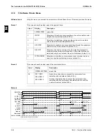
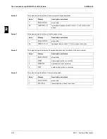
Using this menu you can read the actual value of the software timers. This menu provides 2 screens.
Screen 1
This screen shows the actual value of the general timers.
Screen 2
This screen shows the actual value of the compressor timers.
Example
Line n°
Display
Description
1
GENERAL TIMERS
screen title
2
LOADUP
Delay timer for load up; during countdown, the unit is unable to enter
a higher thermostat step (default: 180 s).
2
DWN
Delay timer for loaddown; during countdown, the unit is unable to
enter a lower thermostat step (default: 20 s).
3
FLOWSTART
Delay timer to enable a continuous water flow through the evaporator
before start up of the compressor (default: 15 s).
3
FLOWSTOP
Delay timer that starts counting when the water flow through the
evaporator stops during normal operation; if the water flow has not
restarted during the countdown, the unit will shut down (default: 5 s).
4
COMPR. STARTED
Delay timer to start the next compressor; used in manual mode or
when only one thermostat step is set up (default: 5 s).
Line n°
Display
Description
1
COMPRESSOR TIMERS
screen title
2-4
GRD 1 AREC 1
GRD 2 AREC 2
GRD 3 AREC 3
Guard timer: delay timer to prevent the compressor from
restarting after a shutdown (default: 60 s).
Anti recycling: delay timer to prevent the compressor from
restarting after the compressor has started; used to limit the
number of restarts (default: 240 s).
180 s
20 s
15 s
15 s
20 s
60 s
60 s
60 s
60 s
5 s
20 s
5 s
3 s ( < 5 s )
6 s ( > 5 s )
20 s
5 s
5 s
240 s
240 s
180 s
180 s
240 s
240 s
180 s
operation
flow
compr. 1
compr. 2
flow start
flow stop
arec 1
guard 1
arec 2
guard 2
load up
loaddown
compr. started
all timers show their default values
Summary of Contents for EUWA/Y5-30HB/C(Z)
Page 2: ......
Page 8: ...Introduction ESIE98 06A vi 3 1 4 5...
Page 10: ...ESIE98 06A 1 2 Part 1 System Outline 3 1 1 4 5...
Page 28: ...General Outline ESIE98 06A 1 20 Part 1 System Outline 3 1 1 4 5...
Page 36: ...Piping Layout ESIE98 06A 1 28 Part 1 System Outline 3 1 1 4 5...
Page 52: ...ESIE98 06A Wiring Layout Part 1 System Outline 1 44...
Page 58: ...ESIE98 06A 2 2 Part 2 Functional Description 3 1 2 4 5...
Page 100: ...ESIE98 06A 3 2 Part 3 Troubleshooting 3 1 3 4 5...
Page 134: ...Troubleshooting ESIE98 06A 3 36 Part 3 Troubleshooting 3 1 3 4 5...
Page 136: ...ESIE98 06A 4 2 Part 4 Commissioning and Test Run 3 1 4 5...
Page 142: ...Pre Test Run Checks ESIE98 06A 4 8 Part 4 Commissioning and Test Run 3 1 4 5...


