Installation and operation manual
13
EUWAC5~10FZ
Packaged air-cooled water chillers
4PW14037-1D
Locking the controller keyboard
Once user parameter
h9
is set to
0
, the following advanced features
can no longer be carried out by means of the controller:
■
Modifying direct and user parameters (parameters can be
displayed but not modified),
■
Resetting the timers.
When user parameter
h9
is set to
1
, the above-described advanced
features can be carried out using the controller.
To lock or unlock the controller keyboard, proceed as follows:
1
Enter the list of user parameters.
Parameter code
:d
appears on the display.
2
Select parameter code
h9
using the
A
and/or
Z
key.
3
Press the
R
key to switch to the parameter value.
4
Select the appropriate setting using the
A
and/or
Z
key.
5
Press the
R
key to return to the list of parameter codes.
6
To adjust or to consult other user parameters before saving the
modifications, select another user parameter using the
A
and/
or
Z
key and then repeat from instruction 3 onwards.
7
To save the modifications, press the
E
key. To cancel the
modifications wait approximately 40 seconds.
In the first case, the controller saves the changes, leaves the list
of user parameters and returns to normal operation, displaying
the inlet water temperature.
In the second case, the display starts flashing. Approximately
40
seconds later, the controller leaves the list of user
parameters without saving the modifications. The inlet water
temperature re-appears on the display.
Defining the unit's serial address
To control the unit from a supervisory system, an address card
(optional module) should be installed in the unit. The unit's serial
address required for communication with the supervisory system is
defined by parameter
ha
. The default, limit and step values for the
serial address are:
■
Default value
1
■
Limit values
1
to
16
■
Step value
1
To define the unit's serial address, proceed as follows:
1
Enter the list of user parameters.
Parameter code
:d
appears on the display.
2
Select parameter code
ha
using the
A
and/or
Z
key.
3
Press the
R
key to switch to the parameter value.
4
Select the appropriate setting using the
A
and/or
Z
key.
5
Press the
R
key to return to the list of parameter codes.
6
To adjust or to consult other user parameters before saving the
modifications, select another user parameter using the
A
and/
or
Z
key and then repeat from instruction 3 onwards.
7
To save the modifications, press the
E
key. To cancel the
modifications wait approximately 40 seconds.
In the first case, the controller saves the changes, leaves the list
of user parameters and returns to normal operation, displaying
the inlet water temperature.
In the second case, the display starts flashing. Approximately
40
seconds later, the controller leaves the list of user
parameters without saving the modifications. The inlet water
temperature reappears on the display.
T
ROUBLESHOOTING
This section provides useful information for diagnosing and correct-
ing certain troubles which may occur in the water chiller.
Before starting the trouble shooting procedure, carry out a thorough
visual inspection of the unit and look for obvious defects such as
loose connections or defective wiring.
Before contacting your local Daikin dealer, read this chapter carefully,
it will save you time and money.
When a safety device was activated, stop the unit and find out why
the safety device was activated before resetting it. Under no circum-
stances safety devices may be bridged or changed to a value other
than the factory setting. If the cause of the problem cannot be found,
call your local Daikin dealer.
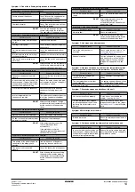
Symptom 1: The unit does not start, but the
T
LED lights up
Symptom 2: The unit does not start, but the
T
LED is flashing
Symptom 3: The unit does not start and the
T
LED does not light up
When carrying out an inspection on the supply panel or on
the switch box of the water chiller, always make sure that
the circuit breaker of the water chiller is switched off.
P
OSSIBLE
CAUSES
C
ORRECTIVE
ACTION
The temperature setting is not
correct.
Check the controller setpoint.
Power supply failure.
Check the voltage on the supply
panel.
Blown fuse or interrupted protection
device.
Inspect fuses and protection
devices. Replace by fuses of the
same size and type. (Refer to the
wiring diagram delivered with the
unit.)
Loose connections.
Inspect connections of the field
wiring and the internal wiring of the
unit. Tighten all loose connections.
Shorted or broken wires.
Test circuits using a tester and repair
if necessary.
P
OSSIBLE
CAUSES
C
ORRECTIVE
ACTION
The flowstart timer is still running
The unit will start after approx. 15
seconds. Make sure that the water is
flowing through the evaporator.
The anti-recycling timer is still active.
The cicuit can only start up after
approximately 4 minutes.
The guard timer is still active.
The circuit can only start up after
approximately 1 minute.
P
OSSIBLE
CAUSES
C
ORRECTIVE
ACTION
One of the following safety devices is
activated:
• Reverse phase protector (R1P)
• Overcurrent relay (K*S)
• Discharge thermal protector (Q*D)
• Evaporating temperature
thermostat (S*T)
• Flow switch (S10L)
• High pressure switch (S*HP)
Check on the controller and refer to
symptom 4
safety devices is activated" on
page 14
. Refer to the explanation of
the digital controller in the chapter
.
The unit is in anti-freeze alarm.
Check on the controller and refer to
symptom 4
safety devices is activated" on
page 14
. Refer to the explanation of
the digital controller in the chapter
.
The remote ON/OFF input is
enabled and the remote switch is off.
Put the remote switch on or disable
the remote ON/OFF input.
The keyboard is locked. The user
parameter
h9
is set to
0
.
Unlock the controller keyboard.
Summary of Contents for EUWAC8FZW1
Page 22: ...4PW14037 1D Copyright Daikin...


