EUWAC5~10FZ
Packaged air-cooled water chillers
4PW14037-1D
Installation and operation manual
8
Digital controller
User interface
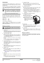
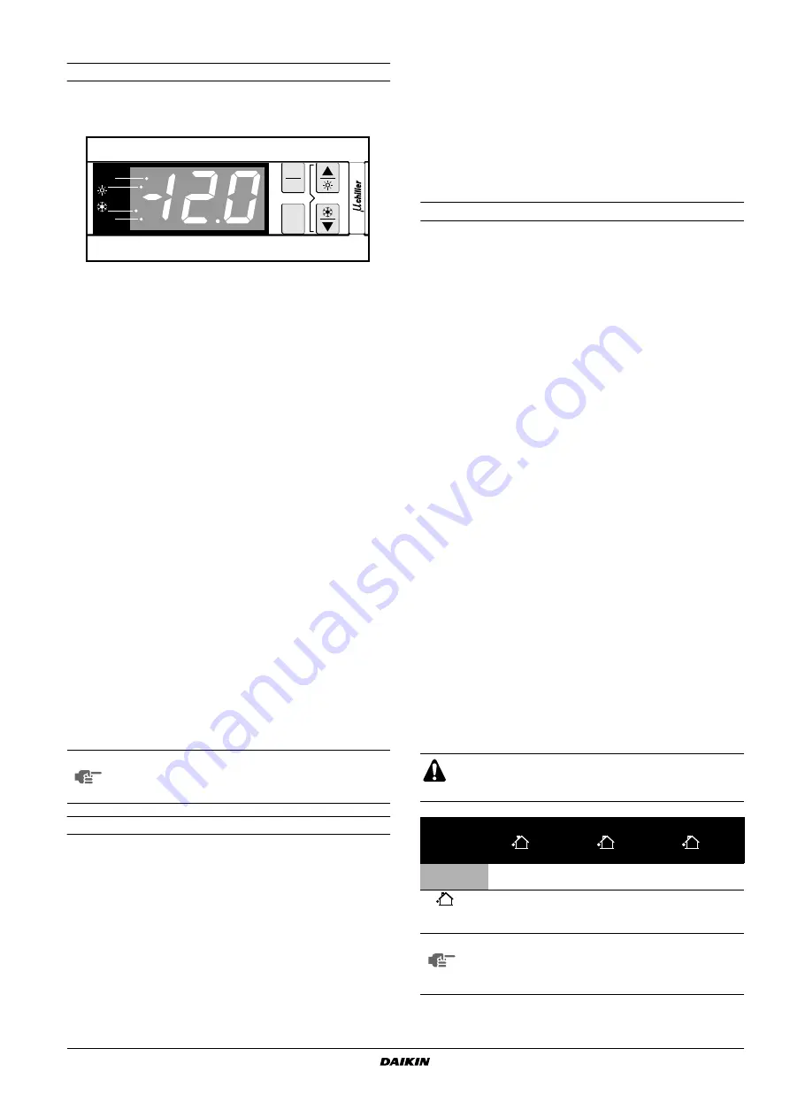
The digital controller consists of a numeric display, four labelled keys
which you can press and four LEDs providing extra user information.
Figure - Digital controller
Keys provided on the controller:
Each key, except for the lower left key, combines two functions:
E
/
O
,
A
/
Y
and
I
/
Z
. The function carried out when the user
presses one of these keys depends on the status of the controller
and the unit at that specific moment.
■
E
key, to enter the scroll list of user parameters, to confirm a
parameter modification and to return to normal operation.
■
O
key, to de-activate the buzzer in the case of an alarm.
■
A
key, to scroll through the list of direct or user parameters or to
raise a setting.
■
Y
key, has no effect on EUWAC units.
■
R
key, to enter the scroll list of direct parameters or to switch
between a parameter's code and its value.
■
I
key, to start the unit in cooling mode or to switch the unit off
when cooling mode is active.
■
Z
key, to scroll through the list of direct or user parameters or to
lower a setting.
LEDs provided on the controller:
The controller provides four LEDs:
■
T
LED, indicates the status of the compressor. The
T
LED
does not light up when the compressor is not active, blinks when
the compressor cannot start up although extra load is requested
(e.g. timer active) and lights up permanently when the compres-
sor is active.
■
Y
LED, is not used.
■
I
LED, indicates that cooling mode is active.
■
U
LED, indicates that the value on the numeric display should
be multiplied by 100.
Direct and user parameters
The digital controller provides direct and user parameters. The direct
parameters are important for the everyday usage of the unit, e.g. to
adjust the temperature setpoint or to consult actual operational
information. The user parameters on the contrary provide advanced
features such as adjusting time delays or disabling the buzzer.
Each parameter is defined by a code and a value. For example, the
parameter used to select local or remote on/off control has code
h7
and value
1
or
0
.
Working with the EUWAC units
This chapter deals with the everyday usage of the EUWAC units.
Here, you will learn how to perform routine tasks, such as:
■
"Switching the EUWAC unit on" on page 8
■
"Adjusting the cooling temperature setpoint" on page 9
■
"Consulting actual operational information" on page 9
,
■
■
"Resetting warnings" on page 10
Switching the EUWAC unit on
To switch the EUWAC unit on, proceed as follows:
1
When the on/off digital input user parameter
h7
is set to
0
(=No),
press the
I
key for approximately 5 seconds to switch the unit
on.
When the on/off digital input user parameter
h7
is set to
1
(=Yes), you can also switch the unit on using the remote on/off
switch (installed by the customer).
In both cases an initialization cycle is started and the
T
LED
starts blinking. The
I
LED lights up, indicating that the unit is
switched on. Once all the timers have reached zero, the unit
starts up and the
T
LED lights up permanently. The numeric
display shows the actual inlet water temperature.
2
When the unit is started up for the first time, or when the unit has
been out of operation for a longer period, it is recommended to
go through the following checklist.
Condenser fan rotation
This check applies to the 10 units only.
As soon as the compressor and the condenser fan have started,
switch off the unit to stop them (refer to
). Check if the fans turn in the right direction
while they are running out. The direction is indicated by an arrow
on the fan housing. If they run in the wrong direction, call your
local Daikin dealer.
Abnormal noise and vibrations
Make sure the unit does not produce any abnormal noises or
vibrations: check the fixations and piping. If the compressor
makes any abnormal noises, this may also be caused by an
overcharge of refrigerant.
Working pressure
It is important to check the high and low pressure of the
refrigerant circuit to ensure the proper operation of the unit and
to guarantee that the rated output will be obtained.
For reference, the average saturated temperature of R407C in
relation to the pressure readout can be found in
NOTE
Temperature readout tolerance: ±1°C.
Legibility of the numeric display may decrease in direct
sunlight.
comp
x
100
clear
PRG
mute
SEL
The pressures measured will vary between a maximum
and minimum value, depending on the water and outdoor
temperatures (at the moment of measurement).
Cooling mode
Minimum
Nominal
Maximum
(
–5°C)
(
35°C)
(
38°C)
(LW 4°C)
(LW 7°C)
(LW 20°C)
Low pressure
3 bar
4 bar
6.5 bar
High pressure
7 bar
21 bar
24 bar
outdoor temperature
LW
leaving water temperature
NOTE
Make sure that the lower service plate is in place when
carrying out the pressure measurements. If not, the
refrigerant will be cooled less in the condenser, which
results in an increase of the low and high pressure.
Summary of Contents for EUWAC8FZW1
Page 22: ...4PW14037 1D Copyright Daikin...


