The Digital Controller
ESIE11-02
2–32
Part 2 – Functional Description
3
1
2
4
5
2.5
Settings: Direct and User Parameters
Direct and user
parameters
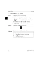
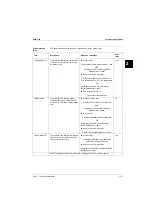
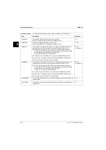
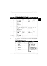
The table below describes the direct and user parameters.
How to access the
parameters
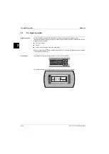
To access the parameters, proceed as follows:
Overview of the
direct and user
parameters
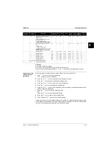
The table below contains an overview of all the parameters. Each parameter is defined by a code and
a value.
Parameters
Description
Example
Direct
Are used for the daily usage of
the unit.
■
To set the cooling temperature set point.
■
To read the operational information.
User
Provide advanced features.
Remote control
To access the… parameters
Press 5 s on…
A password is…
Direct
U
Not required.
Direct and user
U
+
T
Required. Use
22
as password.
Parameter
group
Parameter
code
Description
Default
value
Min
Max
Units
Read/
Write
User/
Direct
Modbus
Address
Parameter
type
a
-
/
-
/23
Measurement unit
0
=°C
1
=°F
0
0
1
R/W
U
5
D
-
a
-
No user or direct parameters accessible
-
b
-
b01
Evaporator inlet water temperature
0.1°C
R
D
102
A
b02
Evaporator outlet water temperature
0.1°C
R
D
103
A
b03
Not used
0.1°C
R
D
104
A
-
c
-
c07
Time delay between pump startup and
compressor startup
15
0
999
1 sec
R/W
U
238
I
c08
Time threshold between the unit shut-
down and the pump shutdown
0
0
150
1 min
R/W
U
239
I
c10
Total running hours of compressor 1
x100 hours R
D
122
A
c11
Total running hours of compressor 2
x100 hours R
D
123
A
c14
Maintenance threshold for mainte-
nance warning (
c10
and
c11
)
0
0
100
x100 hours R/W
U
241
I
c15
Total running hours of pump
x100 hours R
D
126
A
-
d
-
No user or direct parameters accessible
-
f
-
No user or direct parameters accessible
-
h
-
h06
To activate remote cool/heat control
0
=not active
1
=active
(only in case
p09
=
9
)
0
0
1
R/W
U
14
D
h07
To activate remote on/off control
0
=not active
1
=active
(only in case
p34
=
23
)
0
0
1
R/W
U
15
D
h09
To lock the controller keyboard
0
=lock
1
=unlock
1
0
1
R/W
U
16
D
h10
Serial address for BMS connection
1
1
200
R/W
U
256
I
h23
To select address card connection
0
=remote user interface connection
1
=MODBUS connection
0
0
1
R/W
U
11
D
Summary of Contents for EUWY 24KBZW1 Series
Page 2: ......
Page 8: ...ESIE11 02 vi Table of Contents 3 1 4 5...
Page 10: ...Introduction ESIE11 02 viii 3 1 4 5...
Page 12: ...ESIE11 02 1 2 Part 1 System Outline 3 1 1 5...
Page 86: ...Wiring Layout ESIE11 02 1 76 Part 1 System Outline...
Page 88: ...ESIE11 02 2 2 Part 2 Functional Description 3 1 2 5...
Page 128: ...The Digital Controller ESIE11 02 2 42 Part 2 Functional Description 3 1 2 4 5...
Page 130: ...ESIE11 02 3 2 Part 3 Troubleshooting 3 1 3 5...
Page 168: ...ESIE11 02 4 2 Part 4 Commissioning and Test Run 3 1 4 5...
Page 198: ...Test Run and Operation Data ESIE11 02 4 32 Part 4 Commissioning and Test Run 3 1 4 5...
Page 200: ...ESIE11 02 5 2 Part 5 Maintenance 3 1 5...
Page 210: ...ESIE11 02 4 Index 3 1 4 5...

