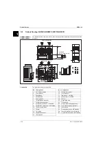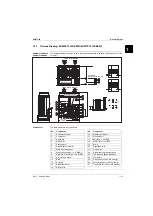
Piping Layout
ESIE11-02
1–62
3
11
4
5
Symbols
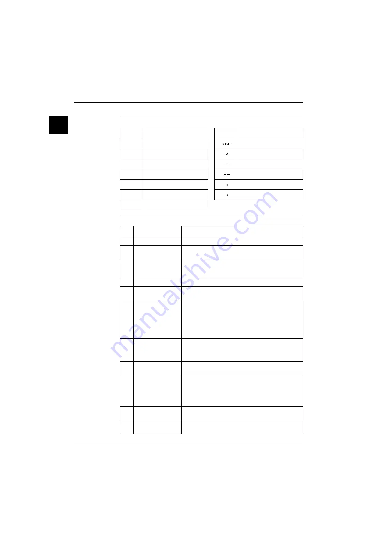
The table below describes the symbols.
Components
refrigeration side
The table below describes the main components of the refrigeration circuit on the refrigeration side.
Symbol
Description
Symbol
Description
R3T
Inlet water temperature sensor
Check valve
R4T
Outlet water temperature sensor
Flare connection
R6T
Ambient temperature sensor
Screw connection
S*HP
High-pressure switch
Flange connection
S*LP
Low-pressure switch
Pinched pipe
M*F
Condensor fan
Spinned pipe
M*C
Compressor
No.
Component
Function / remark
1
Compressor
A hermetically sealed scroll compressor.
2
Water-heat exchanger
(evaporator)
The water-heat exchanger is of the brazed plate-heat
exchanger type.
3
Air-heat exchanger
(condensor)
The air-heat exchanger is of the cross fin coil type. Hi-X-tubes
and PE coated waffle louvre fins are used. The air is discharged
upwards.
4
Fan
Direct driven single or two speed motor.
5
Expansion valve
The thermostatic expansion valve is set up to control the
superheat between 5°C and 7°C.
6
Low-pressure switch
This switch acts as a circuit safety.
■
Standard setting: OFF = 2 bar ± 0.3
■
Standard setting: ON = 0.2 bar ± 0.2
■
Glycol application setting: OFF = 1.5 bar ± 0.3
■
Glycol application setting: ON = 0.5 bar ± 0.2
7
High-pressure switch
This switch acts as a circuit safety.
■
Standard setting: OFF = 21.6 bar +0/-1
■
Standard setting: ON = 30.9 bar +0/-1
8
Strainer
This strainer prevents dirt particles from entering the expansion
valve.
9
Water in- and outlet
connections
The water in- and outlet connections are made of galvanized
steel pipe (British Standard Pipe - BSP). The pipes are not
insulated.
If copper field piping is used for the water circuit, then precau-
tion should be taken to prevent electrolytic corrosion.
10
Low-pressure
service port
The low-pressure service port is used to connect a
low-pressure gauge.
11
High-pressure
service port
The high-pressure service port is used to connect a
high-pressure gauge.
Summary of Contents for EUWY 24KBZW1 Series
Page 2: ......
Page 8: ...ESIE11 02 vi Table of Contents 3 1 4 5...
Page 10: ...Introduction ESIE11 02 viii 3 1 4 5...
Page 12: ...ESIE11 02 1 2 Part 1 System Outline 3 1 1 5...
Page 86: ...Wiring Layout ESIE11 02 1 76 Part 1 System Outline...
Page 88: ...ESIE11 02 2 2 Part 2 Functional Description 3 1 2 5...
Page 128: ...The Digital Controller ESIE11 02 2 42 Part 2 Functional Description 3 1 2 4 5...
Page 130: ...ESIE11 02 3 2 Part 3 Troubleshooting 3 1 3 5...
Page 168: ...ESIE11 02 4 2 Part 4 Commissioning and Test Run 3 1 4 5...
Page 198: ...Test Run and Operation Data ESIE11 02 4 32 Part 4 Commissioning and Test Run 3 1 4 5...
Page 200: ...ESIE11 02 5 2 Part 5 Maintenance 3 1 5...
Page 210: ...ESIE11 02 4 Index 3 1 4 5...


