background image


D

–EIMAC00708-16EN - 9/76 


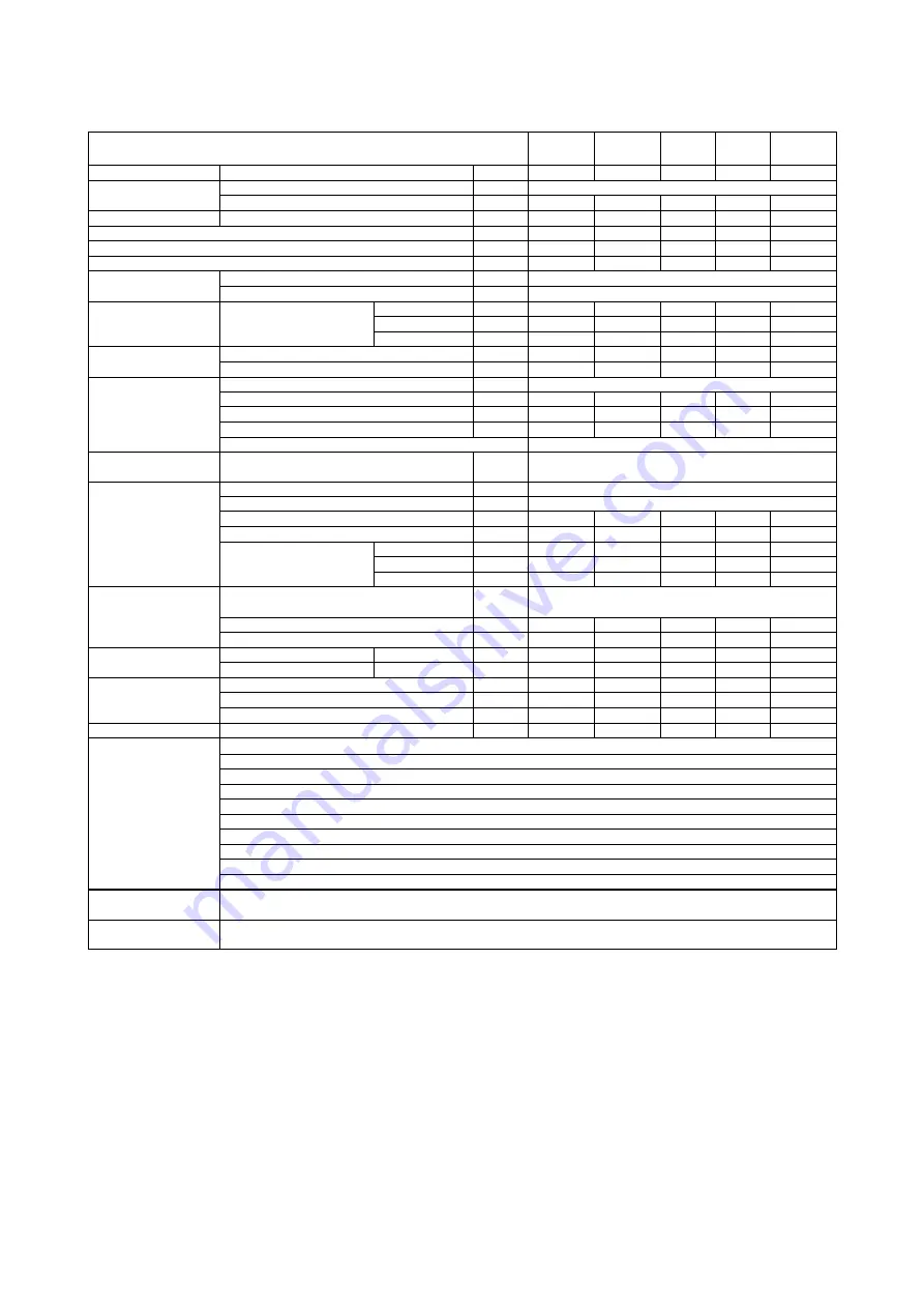
Table 2 - EWAD 210E ÷ 410E-SS - HFC 134a - Technical Data 

Unit SIze 

210 

260 

310 

360 

410 

Capacity (1) 

Cooling 

kW 

214 

256 

307 

360 

413 

Capacity control 

Type 

--- 

Stepless 

Minimum capacity 

25 

25 

25 

25 

25 

Unit power input (1) 

Cooling 

kW 

71.7 

86.7 

111 

133 

146 

EER (1) 

--- 

2.98 

2.95 

2.77 

2.71 

2.84 

ESEER 

--- 

3.02 

3.18 

3.05 

3.23 

3.34 

IPLV 

--- 

3.48 

3.68 

3.57 

3.61 

3.65 

Casing 

Colour 

--- 

Ivory White 

Material 

--- 

Galvanized and painted steel sheet 

Dimensions 

Unit 

Height 

mm 

2273 

2223 

2223 

2223 

2223 

Width 

mm 

1292 

2236 

2236 

2236 

2236 

Length 

mm 

3965 

3070 

3070 

3070 

3070 

Weight 

Unit 

kg 

2086 

2522 

2745 

2855 

2919 

Operating Weight 

kg 

2116 

2547 

2775 

2891 

2963 

Water 

heat 

exchanger 

Type 

--- 

Plate to Plate 

Water volume 

30 

25 

30 

36 

44 

Nominal water flow rate 

l/s 

10.22 

12.22 

14.65 

17.21 

19.74 

Nominal Water pressure drop 

kPa 

21 

48 

48 

48 

45 

Insulation material 

Closed cell 

Air heat exchanger 

Type 

--- 

High efficiency fin and tube type 

with integral subcooler 

Fan 

Type 

--- 

Direct propeller type 

Drive 

--- 

DOL 

Diameter 

mm 

800 

800 

800 

800 

800 

Nominal air flow 

l/s 

21150 

32767 

32767 

31725 

31725 

Model 

Quantity 

No. 

Speed 

rpm 

920 

920 

920 

920 

920 

Motor input 

kW 

1.75 

1.75 

1.75 

1.75 

1.75 

Compressor 

Type 

--- 

Semi-hermetic 

single screw compressor 

Oil charge 

13 

16 

19 

19 

19 

Quantity 

No. 

Sound level 

Sound Power 

Cooling 

dB(A) 

94.2 

94.2 

94.5 

94.5 

95.2 

Sound Pressure (2) 

Cooling 

dB(A) 

75.1 

75.0 

75.3 

75.3 

76.0 

Refrigerant circuit 

Refrigerant type 

--- 

R-134a 

R-134a 

R-134a  R-134a 

R-134a 

Refrigerant charge 

kg. 

33 

46 

46 

56 

60 

N. of circuits 

No. 

Piping connections 

Evaporator water inlet/outlet 

Safety devices 

High discharge pressure (pressure switch) 


High discharge pressure (pressure transducer) 


Low suction pressure (pressure transducer) 


Compressor motor protection 


High discharge temperature 


Low oil pressure 


Low pressure ratio 


High oil filter pressure drop 


Phase monitor 


Water freeze protection controller 

Notes (1) 

Cooling  capacity,  unit  power  input  in  cooling  and  EER  are  based  on  the  following  conditions:  evaporator 
12/7°C; ambient 35°C, unit at full load operation. 

Notes (2) 

The  values  are  according  to  ISO  3744  and  are  referred  to:  evaporator  12/7°C,  ambient  35°C,  full  load 
operation. 


Summary of Contents for EWAD E-SS Series

Page 1: ...Air cooled single circuit screw chiller EWAD100 410 E ERAD120 490 E condensing unit 50 Hz Refrigerant R134a Original Instructions Installation Operation and Maintenance Manual D EIMAC00708 16EN...

Page 2: ...this Manual The entire content is protected by Daikin copyright WARNING Before starting the installation of the unit please read this manual carefully Starting up the unit is absolutely forbidden if a...

Page 3: ...Water pump control 41 Unit On Off remote control Electrical wiring 41 Double Setpoint Electrical wiring 41 External water Setpoint reset Electrical wiring Optional 41 Unit limitation Electrical wirin...

Page 4: ...0E SS 34 Table 17 Electrical Data EWAD 100E 180E SL 35 Table 18 Electrical Data EWAD 210E 400E SL 35 Table 19 Electrical Data ERAD 120E 220E SS 36 Table 20 Electrical Data ERAD 250E 490E SS 36 Table 2...

Page 5: ...ircuit Not Economised units 51 Figure 24 EWAD E SS SL Heat recovery refrigerante circuit Economised units 52 Figure 25 EWAD E SS SL Heat recovery refrigerante circuit Not Economised units 53 Figure 26...

Page 6: ...onnecting it to earth that the model and power supply voltage are as ordered Responsibility for any damage after acceptance of the machine cannot be attributed to the manufacturer Checks Please perfor...

Page 7: ...on inverter Z Inverter Efficiency level McQuay code S Standard efficiency SE X High efficiency XE N A for this range P Premium efficiency PE N A for this range H High ambient HA N A for this range Sou...

Page 8: ...800 800 800 800 800 Nominal air flow l s 10922 10575 16383 15863 21844 Model Quantity No 2 2 3 3 4 Speed rpm 920 920 920 920 920 Motor input kW 1 75 1 75 1 75 1 75 1 75 Compressor Type Semi hermetic s...

Page 9: ...800 800 800 800 800 Nominal air flow l s 21150 32767 32767 31725 31725 Model Quantity No 4 6 6 6 6 Speed rpm 920 920 920 920 920 Motor input kW 1 75 1 75 1 75 1 75 1 75 Compressor Type Semi hermetic...

Page 10: ...m 800 800 800 800 800 Nominal air flow l s 8372 8144 12558 12217 16744 Model Quantity No 2 2 3 3 4 Speed rpm 715 715 715 715 715 Motor input kW 0 78 0 78 0 78 0 78 0 78 Compressor Type Semi hermetic s...

Page 11: ...800 800 800 800 800 Nominal air flow l s 16289 25117 25117 24433 24433 Model Quantity No 4 6 6 6 6 Speed rpm 715 715 715 715 715 Motor input kW 0 78 0 78 0 78 0 78 0 78 Compressor Type Semi hermetic...

Page 12: ...screw compressor Oil charge 3 l 13 13 13 13 13 Quantity No 1 1 1 1 1 Sound level Sound Power Cooling dB A 91 5 91 5 92 3 92 3 93 0 Sound Pressure 2 Cooling dB A 73 5 73 5 73 7 73 7 73 9 Refrigerant c...

Page 13: ...compressor Oil charge 3 l 13 16 19 19 19 Quantity No 1 1 1 1 1 Sound level Sound Power Cooling dB A 94 2 94 2 94 5 94 5 95 2 Sound Pressure 2 Cooling dB A 75 1 75 0 75 3 75 3 76 0 Refrigerant circuit...

Page 14: ...screw compressor Oil charge 3 l 13 13 13 13 13 Quantity No 1 1 1 1 1 Sound level Sound Power Cooling dB A 89 0 89 0 89 8 89 8 90 5 Sound Pressure 2 Cooling dB A 71 0 71 0 71 2 71 2 71 4 Refrigerant ci...

Page 15: ...rew compressor Oil charge 3 l 13 16 19 19 19 Quantity No 1 1 1 1 1 Sound level Sound Power Cooling dB A 91 7 91 7 92 0 92 0 92 7 Sound Pressure 2 Cooling dB A 72 6 72 5 72 8 72 8 73 5 Refrigerant circ...

Page 16: ...64 2 55 5 49 8 76 0 95 2 Note The values are according to ISO 3744 and are referred to units without pumps kit Table 10 Sound levels EWAD E SL ERAD E SL Unit size EWA D Unit size ERA D Sound pressure...

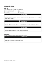
Page 17: ...ed may cause damage to components such as the electronic controller and its LCD display WARNING Storing above the maximum temperature cause opening of the safety valves on the compressors suction line...

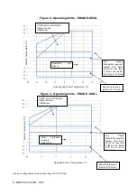
Page 18: ...odulation required below 18 C Amb Temp for less than 3 fans units below 10 C for 3 or more fans units COMP FULL LOAD ONLY Above this line ICE Mode Operation with Glycol below 4 C Evap LWT Saturated Su...

Page 19: ...njury Avoid direct contact Switch off the machine s power supply by opening the main switch before servicing the cooling ventilators and or compressors Failure to observe this rule could result in ser...

Page 20: ...own in the Technical data tables in the General Information chapter refer to standard units Specific machines could have accessories that increase their overall weight pumps heat recovery copper coppe...

Page 21: ...cy and refrigerating capacity Thanks to the geometry of their air cooled condensers the units are less affected by bad air circulation situations Also the software has a particular ability for calcula...

Page 22: ...device must not be positioned at the system s highest point A device that can maintain the hydraulic system under pressure expansion tank etc Water temperature and pressure indicators on the machine...

Page 23: ...connector 3 Temperature probe 4 Isolation Valve 5 Pump 6 Filter Figure 8 Water piping connection for heat recovery exchangers Water treatment Before putting the machine into operation clean the hydra...

Page 24: ...above could result in damage to some of the machine s components Damage from freezing is not covered by the warranty Installing the flow switch To ensure sufficient water flow through the evaporator i...

Page 25: ...following figure Figure 10 Single and twin pump hydronic kit 1 Victaulic joint 2 Water safety valve 3 Connecting manifold 4 Anti freeze electrical resistance 5 Water pump single or twin 6 Automatic fi...

Page 26: ...ternal lift for water pumps kit option on request High lift single pump A EWAD100E SS SL B EWAD120E SS SL C EWAD140E SS EWAD130E SL D EWAD160E SS SL E EWAD180E SS SL F EWAD210E SS SL G EWAD260E SS EWA...

Page 27: ...ternal lift for water pumps kit option on request High lift twin pump A EWAD100E SS SL B EWAD120E SS SL C EWAD140E SS EWAD130E SL D EWAD160E SS SL E EWAD180E SS SL F EWAD210E SS SL G EWAD260E SS EWAD2...

Page 28: ...ne is installed in closed or partly covered areas possible damage from inhalation of refrigerant gases must be avoided Avoid releasing the refrigerant in the environment The safety valves must be conn...

Page 29: ...WAD E SS SL S EWAD100E SS SL T EWAD120E SS SL U EWAD140E SS EWAD130E SL V EWAD160E SS SL W EWAD180E SS SL X EWAD210E SS SL Y EWAD260E SS EWAD250E SL Z EWAD310E SS EWAD300E SL EWAD360E SS EWAD350E SL N...

Page 30: ...tion of toxic phosgene gas which occurs when HFC 134a is exposed to open flame Soft solders are not to be used For copper to copper joints use a phos copper solder with 6 to 8 silver content A high si...

Page 31: ...expected Refrigerant Chargie Pre charge of refrigerant may be evaluate accordingly to the following formula Refrigerant charge kg unit charge as per technical specification tables ld Fl sd Fs Ve 0 5 l...

Page 32: ...th of 10 m They have to be installed to measure the chilles fluid at the inlet WIE and at the outlet WOE of the evaporator and the are used by the unit controller to adjust the unit capacity to the de...

Page 33: ...ll control wires must be connected separately from the power cables Use different electrical passage ducts for this purpose CAUTION Before servicing the machine in any way open the general disconnecti...

Page 34: ...on minimum allowed voltage Maximum current for wires sizing compressors full load ampere fans current x 1 1 Table 16 Electrical Data EWAD 210E 410E SS Unit Size 210 260 310 360 410 Power Supply Phase...

Page 35: ...minimum allowed voltage Maximum current for wires sizing compressors full load ampere fans current x 1 1 Table 18 Electrical Data EWAD 210E 400E SL Unit Size 210 250 300 350 400 Power Supply Phase 3...

Page 36: ...ximum current for wires sizing compressors full load ampere fans current x 1 1 Table 20 Electrical Data ERAD 250E 490E SS Unit Size 250 310 370 440 490 Power Supply Phase 3 3 3 3 3 Frequency Hz 50 50...

Page 37: ...n minimum allowed voltage Maximum current for wires sizing compressors full load ampere fans current x 1 1 Table 22 Electrical Data ERAD 240E 460E SL Unit Size 240 300 350 410 460 Power Supply Phase 3...

Page 38: ...0 A Short circuit rating note 1 25 kA 25 kA 25 kA 25 kA 25 kA Recommended Fuses 125 A gG 160 A gG 160 A gG 200 A gG 200 A gG Minimum Recommended Wire Size note 2 70 mm2 95 mm2 95 mm2 120 mm2 120 mm2 M...

Page 39: ...ect switch terminals In case a larger conductor size is needed contact factory for asking special incoming lugs ERAD 120E 490E SS Model ERAD 120E SS ERAD 140E SS ERAD 170E SS ERAD 200E SS ERAD 220E SS...

Page 40: ...e Note 3 Maximum wire size is the maximum allowed by the disconnect switch terminals In case a larger conductor size is needed contact factory for asking special incoming lugs Connect electrical power...

Page 41: ...occurs in one of the refrigerant circuits Connect terminals 525 526 of the terminal board MC115 to an external visual sound alarm or to the BMS in order to monitor its operation Unit On Off remote co...

Page 42: ...t to induce interference with the electronic controller Current limit The unit load can be varied by means of a 4 20 mA signal released by a BMS In this case a maximum current value must be set on the...

Page 43: ...D EIMAC00708 16EN 43 76 Figure 18 Field Wiring Diagram...

Page 44: ...rmostatic expansion valve with an external equaliser Optionally an electronic expansion valve can be installed which is controlled by an electronic device called Driver that optimises its operation Us...

Page 45: ...ediate pressure and than flows trough an heat exchanger where on the other side flows the remaining part of liquid In this way the soobcooling on the liquid is increased and a small amount of vapour a...

Page 46: ...8 Water inlet connection 6 Built in undercooling section ST1 Suction temperature probe 7 Axial ventilator WL1 Low pressure transducer 0 5 7 0 bar 8 Liquid line isolating tap WO1 Oil pressure transduce...

Page 47: ...mostatic expansion valve 7 Axial ventilator ST1 Suction temperature probe 8 Liquid line isolating tap WL1 Low pressure transducer 0 5 7 0 bar 9 Dehydration filter WO1 Oil pressure transducer 0 0 30 0...

Page 48: ...y of the plant designer Units ar supplied with about 1 barg nitrogen holding charge Figure 21 ERAD 120E 490E SS ERAD 120E 460E SL Not economised refrigerante circuit 1 Single screw compressor 12 Compr...

Page 49: ...ser thermostatic expansion valve 6 Built in undercooling section WL1 Low pressure transducer 0 5 7 0 bar 7 Axial ventilator WO1 Oil pressure transducer 0 0 30 0 bar 8 Liquid line isolating tap WH1 Hig...

Page 50: ...ntrolled by the unit to match the heat demand from the plant the unit load is controlled from the chilled water demand and the heat not consumed by the recovery system is rejected in the condenser coi...

Page 51: ...covery water outlet 8 Liquid line isolating tap ST1 Suction temperature probe 9 Dehydration filter WL1 Low pressure transducer 0 5 7 0 bar 10 Liquid and humidity indicator WO1 Oil pressure transducer...

Page 52: ...et 8 Liquid line isolating tap ST1 Suction temperature probe 9 Dehydration filter WL1 Low pressure transducer 0 5 7 0 bar 10 Liquid and humidity indicator WO1 Oil pressure transducer 0 0 30 0 bar 11 E...

Page 53: ...n 21 Heat recovery water outlet 7 Axial ventilator WL1 Low pressure transducer 0 5 7 0 bar 8 Liquid line isolating tap WO1 Oil pressure transducer 0 0 30 0 bar 9 Dehydration filter WH1 High pressure t...

Page 54: ...y water outlet 7 Axial ventilator WL1 Low pressure transducer 0 5 7 0 bar 8 Liquid line isolating tap WO1 Oil pressure transducer 0 0 30 0 bar 9 Dehydration filter WH1 High pressure transducer 0 0 30...

Page 55: ...re therefore only the main rotor and the satellites that carry out the compression process meshing perfectly together Compression sealing is done thanks to a suitably shaped special composite material...

Page 56: ...by the main rotor Once the flute volume is closed off from the suction chamber the suction stage of the compression cycle is complete 1 2 3 Compression As the main rotor turns the volume of gas trappe...

Page 57: ...by solenoid valves according to inputs from the unit controller Fr3100 compressor having one satellite has one slide only while F3 compressors have two unloding slides The first slide allows to change...

Page 58: ...cuit breakers are kept off both compressors will block due to high pressure when the machine is started up for the first time Resetting the high pressure alarm requires opening the compressor compartm...

Page 59: ...on the display Turn the Q0 switch to the On or 1 position to start the water pump Adjust the water flow until reaching the evaporator design pressure drop Adjust the flow switch not included at this p...

Page 60: ...he lubricating oil and thus avoid the transmigration of refrigerant fluid within It is therefore necessary to ensure that the heaters are powered at least 24 hours before the planned startup time To e...

Page 61: ...nd increase in condensation pressure 14 Check that after the time required for the refrigerant circuit to stabilise the liquid pilot lamp located on the tube leading into the expansion valve is comple...

Page 62: ...achine is to remain inactive during the winter season One must remember that once the machine s power supply has been cut off the antifreeze electrical resistance cannot function Do not leave the evap...

Page 63: ...startup and periodically during operation routine verifications and checks are performed These must also include verification of intake and condensation pressure and the glass pilot lamp place on the...

Page 64: ...cement is advised when its pressure drop exceeds 2 0 bars The pressure drop through the oil filter is the difference between the compressor delivery pressure and the oil pressure Both these pressures...

Page 65: ...achine operating values should be noted daily thus keeping the observation level high 4 Battery cleaning could be more frequently necessary in environments with a high percentage of particles in the a...

Page 66: ...ration however a limited quantity of oil circulates freely in the system conveyed by the refrigerant The quantity of replacement oil going into the compressor should therefore be equal to the quantity...

Page 67: ...water flow through the evaporator for the entire charge discharge time Interrupting the water flow during this procedure would cause the evaporator to freeze with consequent breakage of its internal...

Page 68: ...ween 25 and 100 of the circuit Intake overheating must be between 4 and 6 C Add enough refrigerant to fill the liquid pilot lamp entirely until the passage of bubbles inside stops Add an extra 2 3 kg...

Page 69: ...cessor display It is also used to carry out the OAT setpoint override Compressor delivery pressure transducer This is installed on every compressor and allows to monitor the delivery pressure and to c...

Page 70: ...Ventilators _____ N of expansion valve cycles electronic only _____ Refrigerant Oils pressure Evaporating pressure _____ Bar Condensing pressure _____ Bar Oil pressure _____ Bar Refrigerant temperatur...

Page 71: ...wer supply must not have un unbalance between phases exceeding 3 The machine must stay turned off until the electrical problem has been solved No safety device either mechanica electrical or electroni...

Page 72: ...gerant charge Factory Field h Greenhouse gas emission of the total refrigerant charge expressed as tonnes of CO2 equivalent m Refrigerant type n GWP Global Warming Potential p Unit serial number 2 The...

Page 73: ...rigerant charge Factory Field h Greenhouse gas emission of the total refrigerant charge expressed as tonnes of CO2 equivalent m Refrigerant type n GWP Global Warming Potential p Unit serial number 2 T...

Page 74: ...osal The unit is made of metal and plastic parts All these parts must be disposed of in accordance with the local regulations in terms of disposal Lead batteries must be collected and taken to specifi...

Page 75: ...D EIMAC00708 16EN 75 76...

Page 76: ...of its content and the products and services presented therein Specification are subject to change without prior notice Refer to the data communicated at the time of the order Daikin Applied Europe S...

Reviews: