Operation manual
9
EWAD120~340MBYNN
Packaged air-cooled water chillers
4PW22683-1
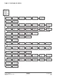
Advanced features of the digital controller
This chapter gives an overview and a brief functional description of
the screens provided by the different menus. In the following chapter,
you will find how you can set up and configure the unit using the
various menu functions.
All menus are directly accessible using the corresponding key on the
digital controller or through the main menu (refer to
). The down arrow
X
on the display indicates that
you can go to the next screen of the current menu using the
h
key.
The up arrow
W
on the display indicates that you can go to the
previous screen of the current menu using the
g
key. If
C
is
displayed, this indicates that you can either return to the previous
screen or can go to the next screen.
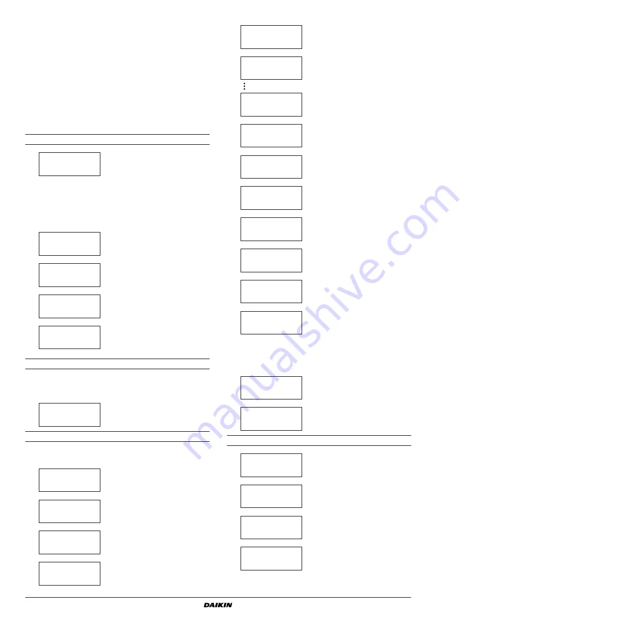
Readout menu
Setpoints menu
Depending upon the settings in the user settings menu, the
"setpoints" menu can either be entered directly or by means of the
user password.
Usersettings menu
The "usersettings" menu, protected by the user password, allows a
full customization of the units.
Timers menu
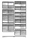
To consult actual operational informa-
tion about the control mode, the inlet
and outlet water temperature (see first
screen).
Note that for a DICN system, the
'()
values
are the values of the individual units,
not of the system. Temperatures of the
system can be consulted in the first
screen of the network menu.
To consult information about the unit
status.
To consult information about the
pressures of circuit 1.
To consult information about the
pressures of circuit 2 (only for
EWAD240~340).
To consult actual operational informa-
tion about the ambient temperature, the
total running hours of the compressor
and the number of compressor starts.
To define the temperature setpoints.
To define the manual settings and to
activate or deactivate manual control
mode.
To define the thermostat settings.
To define the capacity limitations. (first
screen)
To define the capacity limitations.
(second screen)
*+ &%
&%
%!&%
*,
%%%-
*, &
.&%/ 0 1%&2
#&#/ 0 1&
*, &
.&%/ 0 1%&2
#&#/ 0 1&
*3 4
%%%%%5 %%%%%
%%%%%5 %%%%%
%&%
&%
&%
%!&%
%!&
*,
!%- !%-
6 6
*, &
%#27%#7
*,& &
&
%%- %%
%%- %%
*,& &
"%%- %%
#%%- %%
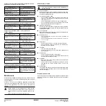
To define the pump control settings.
To define the schedule timer.
According to the settings of
and
following screens will be available or
not.
To define the dual evaporator pump.
To define the floating setpoint.
To define the display settings (first
screen).
To define the display settings (second
screen).
To define the free cooling.
To define the number of slaves for a
“master” unit. This menu can only be
accessed at the "master" unit!
The controller displays the name of the
unit:
,
...
"
. This
name is automatically assigned
depending on the set hardware
address. Refer to "Setting the
adresses" in
"Connection and setup of
a DICN system"
in the installation
manual.
To define wheter or not a password is
needed to enter the setpoints menu.
To enter the service menu (only a
qualified installer is allowed to access
this menu).
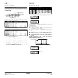
To check the actual value of the general
software timer.
To check the actual value of the
compressor timer. (first screen)
To check the actual value of the
compressor timer. (second screen)
To check the actual value of the
compressor startup timer and the stop
timer.
*,
%%7
%%%7
5%%
*,
*, % %"
%%%%% %%%%
%%%%% %%%%
%"%%%% %%%%
*, &
&
%#25
*,
4& "&%
%"&% %1&%
*,
*,
%%5%%
%%%
*,
*,
*,
%%%%5
*,
*,
%%%%
*+
%%%7%%%7
%%%7
%%7%%7
*,
& %%7
*,
%%%7 %%%7
%%%7 %%%7
*3
%%%7 %%7
%%%7 %%7


