Operation manual
11
EWAD120~340MBYNN
Packaged air-cooled water chillers
4PW22683-1
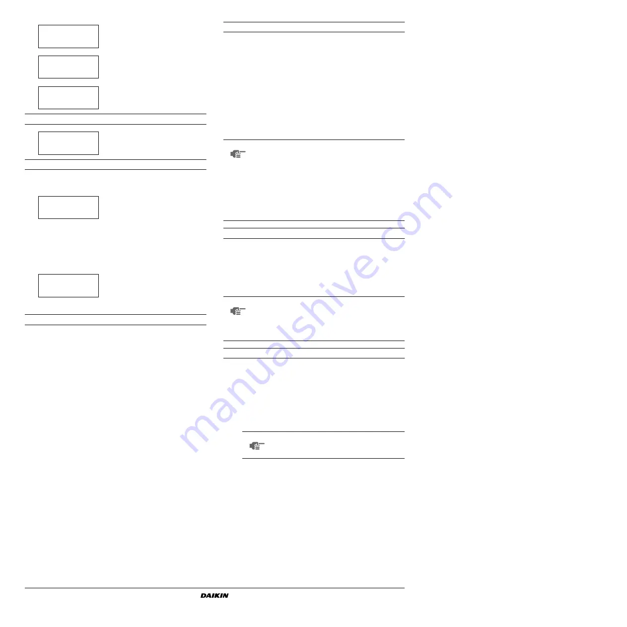
User password menu
Network menu
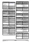
The "network" menu provides useful information regarding the
network.
Tasks of the user settings menu
Entering the user settings menu
The user settings menu is protected by the user password, a 4-digit
number between
%%%%
and
....
.
1
Enter the
&
(Refer to the chapter
).
The controller will request the password.
2
Enter the correct password using the
g
and
h
keys.
3
Press
q
to confirm the password and to enter the user settings
menu.
The controller automatically enters the first screen of the user
settings menu.
To define settings of a certain function:
1
Go to the appropriate screen of the usersettings menu using the
g
and
h
keys.
2
Position the cursor behind the parameter to be modified using
the
q
key.
3
Select the appropriate setting using the
g
and
h
keys.
4
Press
q
to confirm the selection.
When the selection has been confirmed, the cursor switches to
the next parameter which can now be modified.
5
Repeat from instruction 2 onwards to modify the other
parameters.
Defining and activating the control mode
The unit is equipped with a thermostat which controls the cooling
capacity of the unit. Three different control modes exist:
■
manual control mode: the operator controls the capacity
himself -
- by setting:
•
6
,
6
(air flow in manual mode): off, low, medium or high of
circuit 1/2.
•
/
(capacity step in manual mode): 0%, 30%~100% of
circuit 1/2.
■
inlet control mode: uses the evaporator entering water
temperature to control the capacity of the unit -
■
outlet control mode: uses the evaporator leaving water
temperature to control the capacity of the unit -
Defining the thermostat settings
When automatic control mode is selected, the unit uses a thermostat
function to control the cooling capacity. However, the thermostat
parameters are not fixed and can be modified via the
&
screen of the user settings menu.
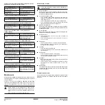
The default, limit and step values for the thermostat parameters are
shown in
Defining the capacity limitation settings
In the
& &
screen up to four possible capacity
limitation settings can be configured.
A capacity limitation can be activated:
■
:
•
see
"Defining the schedule timer" on
•
when a changeable input is configured as
capacity limitation.
•
: to activate capacity limitation 1.
•
: the capacity limitation is not active.
■
"#
/
: capacity limitation value of circuit 1/2 in
case of capacity limitation 1/2/3/4.
To check the status of the fanspeed
relays of circuit
2 (only for
EWAD240~340).
To check the status of the pump, the
alarm and the evaporator heater voltage
free contacts.
To check the status of the changeable
relay output.
To change the user password.
To consult the temperature setpoint, the
common entering water temperature
(entering water temperature of the
master unit) and the common leaving
water temperature (only displayed when
L mode is set and the
optional common leaving water sensor
(R8T) is installed). Refer to
and activating the control mode" on
page 11
The status screen of the network menu
shows the condition of the master unit
(
) and slave units (
...
"
).
*,
"
*,
&
*3&
#
&&
%%-
*,
%%%%
%%%%
*+
&%
&%
*, %%-
%%-
&%%%-
" %%%-
NOTE
To activate manual control mode, select
as
present mode. To deactivate the manual control mode,
select
or
as present
mode.
For units in a DICN configuration:
When changing the control mode on one of the units, it
is automatically transferred to all other units.
Manual control mode however can only be selected on
units with status
.
NOTE
■
If changed on one of the units in a DICN
configuration, this setting is transferred to all other
units in the network.
■
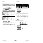
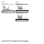
A functional diagram showing the thermostat
parameters can be found in
NOTE
Refer to “Customization in the service menu”,
chapter “Setting of the changeable digital inputs
and outputs” in the installation manual


