Operation manual
17
EWAD120~340MBYNN
Packaged air-cooled water chillers
4PW22683-1
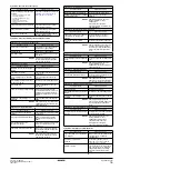
Symptom 7: Unit runs continuously and the water temperature remains
higher than the temperature set on the controller
Symptom 8: Excessive noises and vibrations of the unit
Symptom 9: The display shows
(only in a DICN system)
Symptom 10: The
message shows
&
10
Symptom 11: The alarm message shows
&
11
Symptom 12: The alarm message shows
&
12
Symptom 13: Sensor or transmitter error
13
Symptom 14: The alarm message shows
4 &
14
M
AINTENANCE
In order to ensure optimal availability of the unit, a number of checks
and inspections on the unit and the field wiring have to be carried out
at regular intervals.
If the unit is used for air conditioning application, the described
checks must be executed at least once a year. In case the unit is
used for other applications, the checks must be executed every
4 months.
Maintenance activities
■
Air heat exchanger
Remove dust and any other contaminant from the coil fins using
a brush and a blower. Blow from the inside of the unit. Take care
not to bend or damage the fins.
■
Field wiring and power supply
•
Check the power supply voltage on the local supply panel. The
voltage must correspond to the voltage marked on the identifi-
cation label of the unit.
•
Check the connections and make sure they are properly fixed.
•
Check the proper operation of the circuit breaker and the earth
leak detector provided on the local supply panel.
■
Internal wiring of the unit
Visually check the switch boxes on loose connections (terminals
and components). Make sure that the electrical components are
not damaged or loose.
■
Earth connection
Make sure that the earth wires are still connected properly and
that the earth terminals are tightened.
■
Refrigerant circuit
•
Check for leaks inside the unit. In case a leak is detected, call
your local dealer.
•
Check the working pressure of the unit. Refer to
■
Compressor
•
Check on oil leaks. If there is an oil leak, call your local dealer.
•
Check for abnormal noises and vibrations. If the compressor is
damaged, call your local dealer.
■
Fan motor
•
Clean the cooling ribs of the motor.
•
Check on abnormal noises. If the fan or motor are damaged, call
your local dealer.
■
Water supply
•
Check if the water connection is still well fixed.
•
Check the water quality (refer to the installation manual of the unit
for specifications of the water quality).
■
Waterfilters
•
Make sure to clean the waterfilter in front of the evaporator water
inlet once every 4 months.
•
Check the filter for any possible damage and make sure that the
hole diameter size all over the filter surface is still 1.0 mm
maximum.
■
Water sensors
Check that all the water sensors are correctly fixed into the pipes
in front of the heat exchanger (see also the sticker attached to
the heat exchanger).
Disposal requirements
Dismantling of the unit, treatment of the refrigerant, of oil and of other
parts must be done in accordance with relevant local and national
legislation.
P
OSSIBLE
CAUSES
C
ORRECTIVE
ACTION
The temperature setting on the
controller is too low.
Check and adjust the temperature
setting.
The heat production in the water
circuit is too high.
The cooling capacity of the unit is too
low. Call your local dealer.
Waterflow is too high.
Recalculate the waterflow.
P
OSSIBLE
CAUSES
C
ORRECTIVE
ACTION
Unit has not been fixed properly.
Fix the unit as described in the
installation manual.
P
OSSIBLE
CAUSES
C
ORRECTIVE
ACTION
The adresses set on the PCB or
controller are wrong.
Make sure to set the correct
adresses. Refer to "Setting the
adresses"
in the installation manual.
P
OSSIBLE
CAUSES
C
ORRECTIVE
ACTION
A unit can not be found by the DICN
system.
Make sure all units in the DICN
system are powered or make sure
the correct number of slaves is
defined in the master unit.
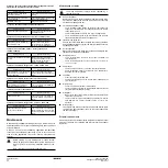
P
OSSIBLE
CAUSES
C
ORRECTIVE
ACTION
The control motor is not reacting due
to bad wiring to the motor or the
motor is damaged.
Check if the wiring to the control
motor is correct and not damaged or
loose.
P
OSSIBLE
CAUSES
C
ORRECTIVE
ACTION
The control motor is operating in
reverse due to wrong wiring.
Check if the wiring is according to
the wiring diagram.
P
OSSIBLE
CAUSES
C
ORRECTIVE
ACTION
The wiring is wrong.
Check if the wiring is according to
the wiring diagram. Call your local
dealer.
P
OSSIBLE
CAUSES
C
ORRECTIVE
ACTION
The expansion board controller
(A11P) can not be found.
Check if the wiring to the expansion
board controller (A11P) is according
to the wiring diagram. Call your local
dealer.
Before carrying out any maintenance or repair activity,
always switch off the circuit breaker on the supply panel,
remove the fuses or open the protection devices of the
unit.
Never clean the unit with water under pressure.
The wiring and power supply must be checked by a
licensed electrician.


