background image

Operation manual

3

EWAD120~340MBYNN

Packaged air-cooled water chillers

4PW22683-1

Function of the main components

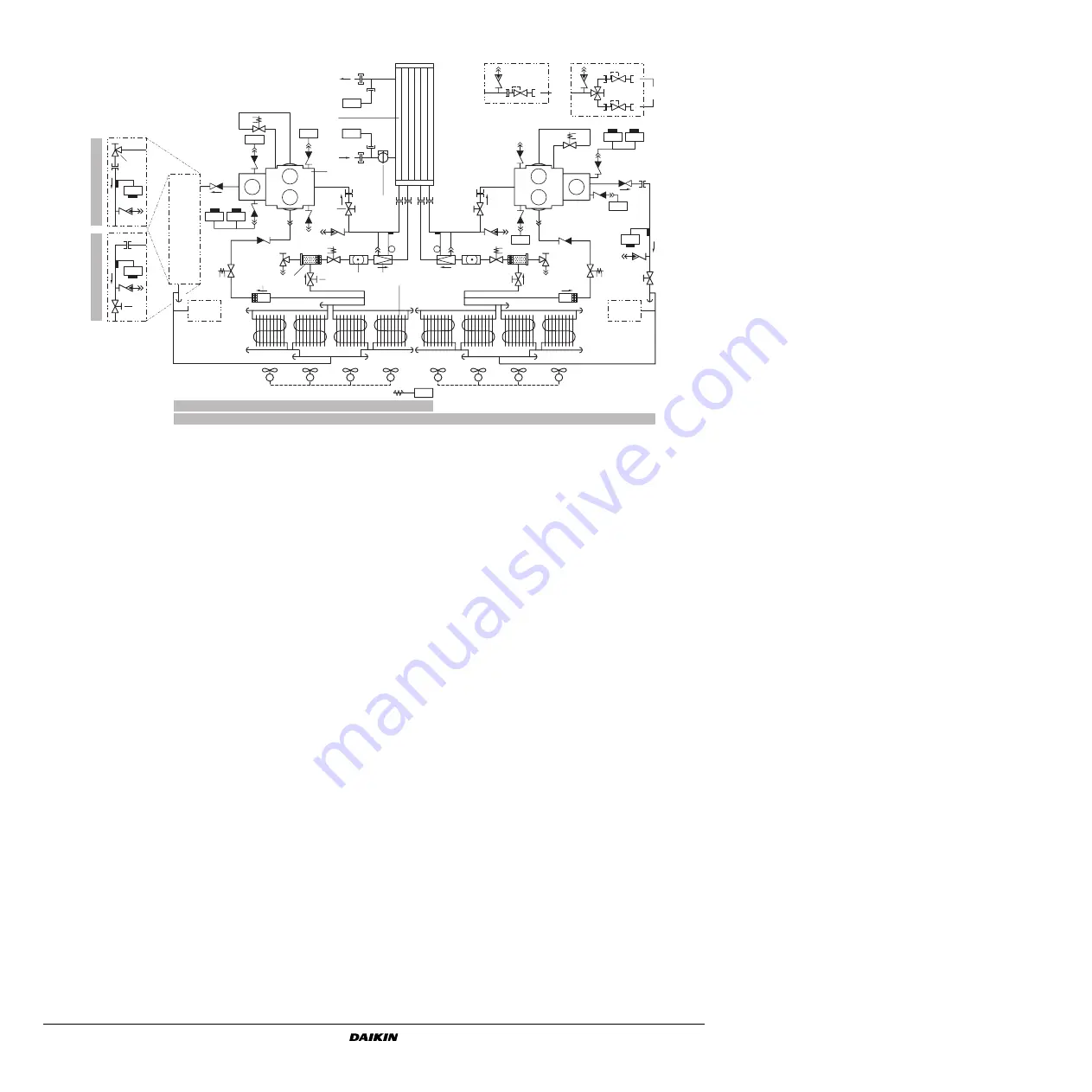
Figure - Functional diagram 

As the refrigerant circulates through the unit, changes in its state or
condition occur. These changes are caused by the following main
components:

Compressor
The compressor (M*C) acts as a pump and circulates the refri-
gerant in the refrigeration circuit. It compresses the refrigerant
vapour coming from the evaporator at the pressure at which it
can easily be liquefied in the condenser.

Condenser
The function of the condenser is to change the state of the
refrigerant from gaseous to liquid. The heat gained by the gas in
the evaporator is discharged through the condenser to the
ambient air, and the vapour condenses to liquid.

Filter/drier
The filter installed behind the condenser removes small particles
from the refrigerant to prevent blockage of the tubes.
The drier takes the water out of the system.

Expansion valve
The liquid refrigerant coming from the condenser enters the
evaporator via an expansion valve. The expansion valve brings
the liquid refrigerant to a pressure at which it can easily be
evaporated in the evaporator.

Evaporator
The main function of the evaporator is to take heat from the
water that flows through it. This is done by turning the liquid
refrigerant, coming from the condenser, into gaseous
refrigerant.

Water in/outlet connection
The water inlet and outlet connection allow an easy connection
of the unit to the water circuit of the air handling unit or industrial
equipment.

Flowswitch
The flowswitch protects the evaporator of the unit against
freezing when there is no waterflow or when the waterflow is too
low.

Safety devices

The unit is equipped with three kinds of safety device:

1

General safety devices

General safety devices shut down all circuits and stop the whole
unit. For this reason the unit has to be manually put on again
after a general safety occurred.

2

Circuit safety devices

Circuit safety devices shut down the circuit they protect, while
the other circuits remain activated.

3

Part safety devices

Part safety devices shut down the part they protect.

An overview of all safety devices is given below.

Overcurrent relay (circuit safety devices)
The overcurrent relays (K*S) are located in the switchbox of the
unit and protect the compressor motors in case of overload,
phase failure or too low voltage. The relays are factory-set and
may not be adjusted. When activated, they must be reset
manually, followed by a reset of the controller.

Compressor thermal protectors (circuit safety devices)
The compressor motors are equipped with thermal protectors
(Q*M). The protectors are activated when the compressor motor
temperature becomes too high. 
When temperature returns to normal, the protectors reset
automatically, but the controller needs to be reset manually.

Y14S

Y15S

B1P

B2P

M1C

R3T

R5T

Y11S

R4T

S14PH

S1PH

Y24S

Y25S

B5P

S4T

M2C

Y21S

S15PH

S2PH

1

2

3

4

5

8

12

9

14

13

10

11

B4P

S3T

6

6

(*)

(*)

A

7

B

7

EWAD240~340

EWAD120~170

S3T

EW

AD120~170

EW

AD240~340

1

Water outlet

7

Safety valve

13

Flowswitch

2

Evaporator

8

Strainer

14

Condenser

3

Water inlet

9

Drier/charge valve

A

Standard

4

Compressor

10

Liquid stop valve

B

Dual pressure relief valve

5

Suction stop valve (optional)

11

Sightglass

(*)

Standard (see A) or optional dual 
pressure relief valve (see B)

6

Discharge stopvalve

12

Expansion valve

Summary of Contents for EWAD120MBYNN1

Page 1: ...OPERATION MANUAL EWAD120MBYNN1 EWAD150MBYNN1 EWAD170MBYNN1 EWAD240MBYNN1 EWAD300MBYNN1 EWAD340MBYNN1 Packaged air cooled water chillers...

Page 2: ...e that it has been properly installed It is therefore necessary to carefully read the installation manual supplied with the unit and the recommendations listed in Checks before initial start up on pag...

Page 3: ...rge evaporator 19 Field wiring intake 2 Condenser 11 Leaving water temperature sensor R4T 20 Main isolator switch optional S13S 3 Compressor 1 M1C 12 Entering water temperature sensor R3T 21 Compresso...

Page 4: ...the evaporator of the unit against freezing when there is no waterflow or when the waterflow is too low Safety devices The unit is equipped with three kinds of safety device 1 General safety devices...

Page 5: ...ntroller A11P Expansion board controller only for EWAD240 340 B1P B4P Low pressure transmitter for circuit 1 circuit 2 B2P B5P High pressure transmitter for circuit 1 circuit 2 C1 C3 Capacitor E1HC E2...

Page 6: ...ted by paper sheets cardboard or any other material 12 Power supply voltage Check the power supply voltage on the local supply panel The voltage should correspond to the voltage on the identification...

Page 7: ...with the everyday usage of the unit Here you will find how to perform routine tasks such as Setting the language on page 6 Switching the unit on on page 7 Consulting actual operational information on...

Page 8: ...rs menu on page 9 the circuit is ready to start up when extra cooling load is needed The preceding OFF messages are written down in order of priority If one of the timers is busy and one of the safeti...

Page 9: ...ll function as stand alone units If a slave unit can not be found by the network the red light inside the p key of the master lights up and the buzzer inside the control is activated If the master can...

Page 10: ...atus To consult information about the pressures of circuit 1 To consult information about the pressures of circuit 2 only for EWAD240 340 To consult actual operational informa tion about the ambient t...

Page 11: ...f the compressors at the moment of shutdown To check which were the pressures of the circuit 1 at the moment of shutdown To check which were the pressures of the circuit 2 at the moment of shutdown on...

Page 12: ...e cooling capacity However the thermostat parameters are not fixed and can be modified via the screen of the user settings menu The default limit and step values for the thermostat parameters are show...

Page 13: ...ating setpoint is altered based on the ambient temperature 4 used to define maximum value that can be added to the active setpoint used to define the ambient source at which the floating setpoint valu...

Page 14: ...tep change has occurred During the countdown the unit will not be able to go to a lower thermo stat step FLOWSTART 15 sec counts down when the waterflow through the evaporator is continuous and the un...

Page 15: ...to consult the first screen This screen contains information about the unit name and the refrigerant used 3 Press h to consult the next screen This screen contains information about the controller s...

Page 16: ...devices may be bridged or changed to a value other than the factory setting If the cause of the problem cannot be found call your local dealer Symptom 1 The unit does not start but the ON LED lights...

Page 17: ...sed electrician RESET After pressure decrease push the button on the high pressure switch and reset the controller Symptom 5 4 Fan thermal protector is activated POSSIBLE CAUSES CORRECTIVE ACTION Mech...

Page 18: ...ck the water quality refer to the installation manual of the unit for specifications of the water quality Waterfilters Make sure to clean the waterfilter in front of the evaporator water inlet once ev...

Page 19: ...ngs in group 1 all Wednesdays will work according to the settings in group 2 all Saturdays and Sundays will work according to the settings in group 3 all holiday days will work according to the settin...

Page 20: ...tween inlet water evaporator temperature and ambient temperature Floating setpoint Default value Lower limit Upper limit Maximum value C 3 0 0 0 5 0 D1 C 20 0 20 0 43 0 D2 a a rise in floating setpoin...

Page 21: ...h h g h g h 0 1 2 0 1 g h g h g h g h g h g h g h g h g h g g h g h g h g h g h h g g 5 f 2 7 7 g h 7 7 5 7 7 7 7 7 7 7 7 7 7 3 7 7 7 7 g h g h g h 5 0 1 2 0 1 5 5 5 0 1 2 0 1 5 5 q h h g q h g h g h...

Page 22: ...Zandvoordestraat 300 B 8400 Oostende Belgium 4PW22683 1...

Reviews: