General Outline
ESIE10-01
1–98
3
11
4
5
Controlling the
partial recovery
circuit and
installation
recommendations
The partial heat recovery system is not managed and/or controlled by the machine. The installer
should follow the suggestions below for best system performance and reliability:
1. Install a mechanical filter on the heat exchanger inlet pipe.
2. Install shut-off valves to isolate the heat exchanger from the water system during periods of inac-
tivity or system maintenance.
3. Install a drain valve that allows the heat exchanger to be emptied in the event that air temperature
is expected to fall below 0°C during periods of machine inactivity.
4. Install flexible anti-vibration joints on the heat recovery water inlet and outlet piping, so that trans-
mission of vibrations, and therefore noise, to the water system is kept as low as possible.
5. Do not load exchanger joints with the weight of the heat recovery piping. The water joints of the
exchangers are not designed to support the weight.
6. Should heat recovery water temperature be lower than ambient temperature, it is advised to
switch off the heat recovery water pump 3 minutes after having switched off the last compressor.
Important:
Partial heat recovery, which exploits the post-overheating cooling of the delivery gas, is
designed as a source to integrate an external heating source. Recovery availability is only guaranteed
with the refrigerating circuit operating upon request of the refrigerated water circuit. Specifically, it is
not suitable for operation with exchanger water inlet temperatures of below 40°C for periods in excess
of normal system operation (approx. 30 minutes). Prolonged operation in these conditions can lead to
malfunctions of the refrigerating circuit and the intervention of the protective devices. The installer
must ensure that the recovery circuit water reaches the minimum value admitted as quickly as
possible. This is also why the lack of water flow must be ensured in the exchanger when the
refrigerating circuit is not running.
Summary of Contents for EWAD620-C17C-SL
Page 2: ......
Page 8: ...ESIE10 01 1 2 Part 1 System Outline 3 1 1 5 ...
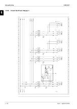
Page 111: ...ESIE10 01 General Outline Part 1 System Outline 1 105 3 1 4 5 1 36 1 Power Compressor 1 2 ...
Page 112: ...General Outline ESIE10 01 1 106 Part 1 System Outline 3 1 1 4 5 1 36 2 Power Compressor 3 ...
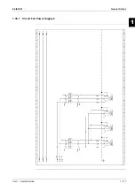
Page 113: ...ESIE10 01 General Outline Part 1 System Outline 1 107 3 1 4 5 1 36 3 Kit Pumps ...
Page 122: ...General Outline ESIE10 01 1 116 Part 1 System Outline 3 1 1 4 5 1 36 12 Digital Inputs Board ...
Page 123: ...ESIE10 01 General Outline Part 1 System Outline 1 117 3 1 4 5 1 36 13 Digital Outputs Board ...
Page 124: ...General Outline ESIE10 01 1 118 Part 1 System Outline 3 1 1 4 5 1 36 14 Digital Outputs Board ...
Page 131: ...ESIE10 01 General Outline Part 1 System Outline 1 125 3 1 4 5 1 36 21 EEXV Compressor 1 ...
Page 134: ...General Outline ESIE10 01 1 128 Part 1 System Outline 3 1 1 4 5 1 36 24 EEXV Compressor 2 ...
Page 137: ...ESIE10 01 General Outline Part 1 System Outline 1 131 3 1 4 5 1 36 27 EEXV Compressor 3 ...
Page 138: ...General Outline ESIE10 01 1 132 Part 1 System Outline 3 1 1 4 5 1 36 28 Pumps Control ...
Page 139: ...ESIE10 01 General Outline Part 1 System Outline 1 133 3 1 4 5 1 36 29 Terminals M1 M2 ...
Page 140: ...General Outline ESIE10 01 1 134 Part 1 System Outline 3 1 1 4 5 1 36 30 Terminals M3 ...
Page 141: ...ESIE10 01 General Outline Part 1 System Outline 1 135 3 1 4 5 1 36 31 Terminals M5 MQ ...
Page 148: ...General Outline ESIE10 01 1 142 Part 1 System Outline 3 1 1 4 5 ...
Page 150: ...ESIE10 01 2 2 Part 2 Functional Description 3 1 2 5 ...
Page 170: ...The Digital Controller ESIE10 01 2 22 Part 2 Functional Description 3 1 2 4 5 ...
Page 200: ...Functional Control ESIE10 01 2 52 Part 2 Functional Description 3 1 2 4 5 ...
Page 202: ...ESIE10 01 3 2 Part 3 Troubleshooting 3 1 3 5 ...
Page 254: ...Alarms and Events ESIE10 01 3 54 Part 3 Troubleshooting 3 1 3 4 5 ...
Page 266: ...Controller Inputs and Outputs ESIE10 01 3 66 Part 3 Troubleshooting 3 1 3 4 5 ...
Page 280: ...ESIE10 01 4 2 Part 4 Commissioning and Test Run 3 1 4 5 ...
Page 286: ...Pre Test Run Checks ESIE10 01 4 8 Part 4 Commissioning and Test Run 3 1 4 5 ...
Page 289: ...ESIE10 01 Running Data Part 4 Commissioning and Test Run 4 11 3 4 5 1 ...
Page 290: ...Running Data ESIE10 01 4 12 Part 4 Commissioning and Test Run 3 1 4 5 ...


