The Digital Controller
ESIE10-01
2–18
Part 2 – Functional Description
3
1
2
4
5
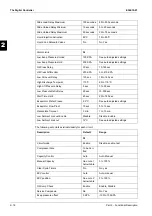
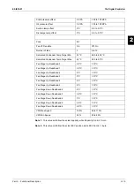
The following set points exist individually for each circuit:
Slide Load Delay Maximum
150 seconds
60 to 300 seconds
Slide Unload Delay Minimum
10 seconds
5 to 20 seconds
Slide Unload Delay Maximum
50 seconds
30 to 75 seconds
Liquid Injection Activation
85°C
75 to 90°C
Liquid Line Solenoid Valves
No
No, Yes
Alarm Limits
SI
Low Evap Pressure-Unload
190 KPA
See auto adjusted settings
Low Evap Pressure-Hold
200 KPA
See auto adjusted settings
Oil Press Delay
30 sec
10-180 sec
Oil Press Differential
250 KPA
0 to 415 KPA
Low Oil Level Delay
120 sec
10 to 180 sec
High Discharge Temperat.
110°C
65 to 110°C
High Lift Pressure Delay
5 sec
0 to 30 sec
Low Pressure Ratio Delay
90 sec
30-300 sec
Start Time Limit
60 sec
20 to 180 sec
Evaporator Water Freeze
2.2°C
See auto adjusted settings
Evaporator Flow Proof
15 sec
5 to 15 sec
Recirculate Timeout
3 min
1 to 10 min
Low Ambient Lockout Enable
Disable
Disable, Enable
Low Ambient Lockout
12°C
See auto adjusted settings
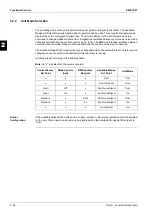
Description
Default
Range
SI
Circuit mode
Enable
Disable, enable, test
Compressor Size
To be Veri-
fied
Capacity Control
Auto
Auto, Manual
Manual Capacity
See note 1
below table
0 to 100%
Clear Cycle Timers
No
No, yes
EXV control
Auto
Auto, manual
EXV position
See note 2
below table
0 to 100%
Oil Sump Check
Enable
Enable, Disable
Service Pumpdown
No
No, Yes
Evap pressure offset
0 KPA
-100 to 100 KPA
Summary of Contents for EWAD620-C17C-SL
Page 2: ......
Page 8: ...ESIE10 01 1 2 Part 1 System Outline 3 1 1 5 ...
Page 111: ...ESIE10 01 General Outline Part 1 System Outline 1 105 3 1 4 5 1 36 1 Power Compressor 1 2 ...
Page 112: ...General Outline ESIE10 01 1 106 Part 1 System Outline 3 1 1 4 5 1 36 2 Power Compressor 3 ...
Page 113: ...ESIE10 01 General Outline Part 1 System Outline 1 107 3 1 4 5 1 36 3 Kit Pumps ...
Page 122: ...General Outline ESIE10 01 1 116 Part 1 System Outline 3 1 1 4 5 1 36 12 Digital Inputs Board ...
Page 123: ...ESIE10 01 General Outline Part 1 System Outline 1 117 3 1 4 5 1 36 13 Digital Outputs Board ...
Page 124: ...General Outline ESIE10 01 1 118 Part 1 System Outline 3 1 1 4 5 1 36 14 Digital Outputs Board ...
Page 131: ...ESIE10 01 General Outline Part 1 System Outline 1 125 3 1 4 5 1 36 21 EEXV Compressor 1 ...
Page 134: ...General Outline ESIE10 01 1 128 Part 1 System Outline 3 1 1 4 5 1 36 24 EEXV Compressor 2 ...
Page 137: ...ESIE10 01 General Outline Part 1 System Outline 1 131 3 1 4 5 1 36 27 EEXV Compressor 3 ...
Page 138: ...General Outline ESIE10 01 1 132 Part 1 System Outline 3 1 1 4 5 1 36 28 Pumps Control ...
Page 139: ...ESIE10 01 General Outline Part 1 System Outline 1 133 3 1 4 5 1 36 29 Terminals M1 M2 ...
Page 140: ...General Outline ESIE10 01 1 134 Part 1 System Outline 3 1 1 4 5 1 36 30 Terminals M3 ...
Page 141: ...ESIE10 01 General Outline Part 1 System Outline 1 135 3 1 4 5 1 36 31 Terminals M5 MQ ...
Page 148: ...General Outline ESIE10 01 1 142 Part 1 System Outline 3 1 1 4 5 ...
Page 150: ...ESIE10 01 2 2 Part 2 Functional Description 3 1 2 5 ...
Page 170: ...The Digital Controller ESIE10 01 2 22 Part 2 Functional Description 3 1 2 4 5 ...
Page 200: ...Functional Control ESIE10 01 2 52 Part 2 Functional Description 3 1 2 4 5 ...
Page 202: ...ESIE10 01 3 2 Part 3 Troubleshooting 3 1 3 5 ...
Page 254: ...Alarms and Events ESIE10 01 3 54 Part 3 Troubleshooting 3 1 3 4 5 ...
Page 266: ...Controller Inputs and Outputs ESIE10 01 3 66 Part 3 Troubleshooting 3 1 3 4 5 ...
Page 280: ...ESIE10 01 4 2 Part 4 Commissioning and Test Run 3 1 4 5 ...
Page 286: ...Pre Test Run Checks ESIE10 01 4 8 Part 4 Commissioning and Test Run 3 1 4 5 ...
Page 289: ...ESIE10 01 Running Data Part 4 Commissioning and Test Run 4 11 3 4 5 1 ...
Page 290: ...Running Data ESIE10 01 4 12 Part 4 Commissioning and Test Run 3 1 4 5 ...

