ESIE10-01
The Digital Controller
Part 2 – Functional Description
2–19
3
2
4
5
1
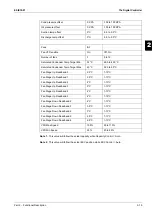
Note 1
- This value will follow the actual capacity while Capacity Control = Auto.
Note 2
- This value will follow the actual EXV position while EXV Control = Auto.
Cond pressure offset
0 KPA
-100 to 100 KPA
Oil pressure offset
0 KPA
-100 to 100 KPA
Suction temp offset
0°C
-5.0 to 5.0°C
Discharge temp offset
0°C
-5.0 to 5.0°C
Fans
SI
Fan VFD enable
On
Off, On
Number of fans
5
5 to 12
Saturated Condenser Temp Target Min
32°C
26.0 to 43.0°C
Saturated Condenser Temp Target Max
43°C
32.0 to 50°C
Fan Stage Up Deadband 0
2.5°C
1-10°C
Fan Stage Up Deadband 1
2.5°C
1-10°C
Fan Stage Up Deadband 2
4°C
1-10°C
Fan Stage Up Deadband 3
5°C
1-10°C
Fan Stage Up Deadband 4
4°C
1-10°C
Fan Stage Up Deadband 5
4°C
1-10°C
Fan Stage Down Deadband 2
4°C
1-13°C
Fan Stage Down Deadband 3
3.5°C
1-13°C
Fan Stage Down Deadband 4
3°C
1-13°C
Fan Stage Down Deadband 5
2.5°C
1-13°C
Fan Stage Down Deadband 6
2.5°C
1-13°C
VFD Max Speed
100%
90 to 110%
VFD Min Speed
25%
20 to 60%
Summary of Contents for EWAD620-C17C-SL
Page 2: ......
Page 8: ...ESIE10 01 1 2 Part 1 System Outline 3 1 1 5 ...
Page 111: ...ESIE10 01 General Outline Part 1 System Outline 1 105 3 1 4 5 1 36 1 Power Compressor 1 2 ...
Page 112: ...General Outline ESIE10 01 1 106 Part 1 System Outline 3 1 1 4 5 1 36 2 Power Compressor 3 ...
Page 113: ...ESIE10 01 General Outline Part 1 System Outline 1 107 3 1 4 5 1 36 3 Kit Pumps ...
Page 122: ...General Outline ESIE10 01 1 116 Part 1 System Outline 3 1 1 4 5 1 36 12 Digital Inputs Board ...
Page 123: ...ESIE10 01 General Outline Part 1 System Outline 1 117 3 1 4 5 1 36 13 Digital Outputs Board ...
Page 124: ...General Outline ESIE10 01 1 118 Part 1 System Outline 3 1 1 4 5 1 36 14 Digital Outputs Board ...
Page 131: ...ESIE10 01 General Outline Part 1 System Outline 1 125 3 1 4 5 1 36 21 EEXV Compressor 1 ...
Page 134: ...General Outline ESIE10 01 1 128 Part 1 System Outline 3 1 1 4 5 1 36 24 EEXV Compressor 2 ...
Page 137: ...ESIE10 01 General Outline Part 1 System Outline 1 131 3 1 4 5 1 36 27 EEXV Compressor 3 ...
Page 138: ...General Outline ESIE10 01 1 132 Part 1 System Outline 3 1 1 4 5 1 36 28 Pumps Control ...
Page 139: ...ESIE10 01 General Outline Part 1 System Outline 1 133 3 1 4 5 1 36 29 Terminals M1 M2 ...
Page 140: ...General Outline ESIE10 01 1 134 Part 1 System Outline 3 1 1 4 5 1 36 30 Terminals M3 ...
Page 141: ...ESIE10 01 General Outline Part 1 System Outline 1 135 3 1 4 5 1 36 31 Terminals M5 MQ ...
Page 148: ...General Outline ESIE10 01 1 142 Part 1 System Outline 3 1 1 4 5 ...
Page 150: ...ESIE10 01 2 2 Part 2 Functional Description 3 1 2 5 ...
Page 170: ...The Digital Controller ESIE10 01 2 22 Part 2 Functional Description 3 1 2 4 5 ...
Page 200: ...Functional Control ESIE10 01 2 52 Part 2 Functional Description 3 1 2 4 5 ...
Page 202: ...ESIE10 01 3 2 Part 3 Troubleshooting 3 1 3 5 ...
Page 254: ...Alarms and Events ESIE10 01 3 54 Part 3 Troubleshooting 3 1 3 4 5 ...
Page 266: ...Controller Inputs and Outputs ESIE10 01 3 66 Part 3 Troubleshooting 3 1 3 4 5 ...
Page 280: ...ESIE10 01 4 2 Part 4 Commissioning and Test Run 3 1 4 5 ...
Page 286: ...Pre Test Run Checks ESIE10 01 4 8 Part 4 Commissioning and Test Run 3 1 4 5 ...
Page 289: ...ESIE10 01 Running Data Part 4 Commissioning and Test Run 4 11 3 4 5 1 ...
Page 290: ...Running Data ESIE10 01 4 12 Part 4 Commissioning and Test Run 3 1 4 5 ...


