Functional Control
ESIE10-01
2–44
Part 2 – Functional Description
3
1
2
4
5
2.3.3
Compressor Control
The compressor should run only when the circuit is in a run or pumpdown state. This means the
compressor should not be running any time the circuit is off or preopening the EXV.
Cycle timers
A minimum time between starts of the compressor and a minimum time between shutdown and start
of the compressor shall be enforced. The time values are set by global circuit set points.
These cycle timers shall be enforced even through cycling of power to the chiller.
Compressor run
timer
When a compressor starts, a timer will start and run as long as the compressor runs. This timer is used
in the alarm log.
Compressor
capacity control
After starting, the compressor should be unloaded to the minimum physical capacity and no attempt
to increase compressor capacity should be made until the differential between evaporator pressure
and oil pressure meets a minimum value.
After the minimum differential pressure is met, compressor capacity shall be controlled to 25%.
■
Auto Capacity Control
Changes to capacity shall be performed as needed to meet unit capacity requirements (see unit
capacity control section).
Capacity shall not be increased above 25% until discharge superheat has been at least 22°F for a
time of at least 30 seconds.
■
Manual capacity control
The capacity of the compressor may be controlled manually. Manual capacity control is to be ena-
bled via a set point with choices of auto or manual. Another set point should allow setting the
compressor capacity from 25% to 100%.
Capacity control shall revert back to automatic control if either:
■
The circuit shuts down for any reason.
■
Capacity control has been set to manual for four hours.
■
Slide Control Solenoids
The required capacity should be achieved by controlling one modulating slide and one non-modu-
lating slide. The modulating slide can control 10% to 50% of the total compressor capacity, infi-
nitely variable. The non-modulating slide can control either 0% or 50% of the total compressor
capacity.
Either the load or the unload solenoid for the non-modulating slide should be on any time the
compressor is running. For compressor capacity from 10% up to 50%, the non-modulating slide
unload solenoid should be on to keep that slide in the unloaded position. For capacity from 60% to
100%, the non-modulating slide load solenoid should be on to keep that slide in the loaded posi-
tion.
The modulating slide should be moved via pulsing of the load and unload solenoids to achieve the
required capacity.
An additional solenoid should be controlled to assist in moving the modulating slide in certain con-
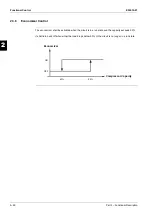
ditions. This solenoid should be activated when the pressure ratio (condenser pressure divided by
evaporator pressure) is less than or equal to 1.2 for at least 5 seconds. It should be deactivated
when pressure ratio is more than 1.2.
Summary of Contents for EWAD620-C17C-SL
Page 2: ......
Page 8: ...ESIE10 01 1 2 Part 1 System Outline 3 1 1 5 ...
Page 111: ...ESIE10 01 General Outline Part 1 System Outline 1 105 3 1 4 5 1 36 1 Power Compressor 1 2 ...
Page 112: ...General Outline ESIE10 01 1 106 Part 1 System Outline 3 1 1 4 5 1 36 2 Power Compressor 3 ...
Page 113: ...ESIE10 01 General Outline Part 1 System Outline 1 107 3 1 4 5 1 36 3 Kit Pumps ...
Page 122: ...General Outline ESIE10 01 1 116 Part 1 System Outline 3 1 1 4 5 1 36 12 Digital Inputs Board ...
Page 123: ...ESIE10 01 General Outline Part 1 System Outline 1 117 3 1 4 5 1 36 13 Digital Outputs Board ...
Page 124: ...General Outline ESIE10 01 1 118 Part 1 System Outline 3 1 1 4 5 1 36 14 Digital Outputs Board ...
Page 131: ...ESIE10 01 General Outline Part 1 System Outline 1 125 3 1 4 5 1 36 21 EEXV Compressor 1 ...
Page 134: ...General Outline ESIE10 01 1 128 Part 1 System Outline 3 1 1 4 5 1 36 24 EEXV Compressor 2 ...
Page 137: ...ESIE10 01 General Outline Part 1 System Outline 1 131 3 1 4 5 1 36 27 EEXV Compressor 3 ...
Page 138: ...General Outline ESIE10 01 1 132 Part 1 System Outline 3 1 1 4 5 1 36 28 Pumps Control ...
Page 139: ...ESIE10 01 General Outline Part 1 System Outline 1 133 3 1 4 5 1 36 29 Terminals M1 M2 ...
Page 140: ...General Outline ESIE10 01 1 134 Part 1 System Outline 3 1 1 4 5 1 36 30 Terminals M3 ...
Page 141: ...ESIE10 01 General Outline Part 1 System Outline 1 135 3 1 4 5 1 36 31 Terminals M5 MQ ...
Page 148: ...General Outline ESIE10 01 1 142 Part 1 System Outline 3 1 1 4 5 ...
Page 150: ...ESIE10 01 2 2 Part 2 Functional Description 3 1 2 5 ...
Page 170: ...The Digital Controller ESIE10 01 2 22 Part 2 Functional Description 3 1 2 4 5 ...
Page 200: ...Functional Control ESIE10 01 2 52 Part 2 Functional Description 3 1 2 4 5 ...
Page 202: ...ESIE10 01 3 2 Part 3 Troubleshooting 3 1 3 5 ...
Page 254: ...Alarms and Events ESIE10 01 3 54 Part 3 Troubleshooting 3 1 3 4 5 ...
Page 266: ...Controller Inputs and Outputs ESIE10 01 3 66 Part 3 Troubleshooting 3 1 3 4 5 ...
Page 280: ...ESIE10 01 4 2 Part 4 Commissioning and Test Run 3 1 4 5 ...
Page 286: ...Pre Test Run Checks ESIE10 01 4 8 Part 4 Commissioning and Test Run 3 1 4 5 ...
Page 289: ...ESIE10 01 Running Data Part 4 Commissioning and Test Run 4 11 3 4 5 1 ...
Page 290: ...Running Data ESIE10 01 4 12 Part 4 Commissioning and Test Run 3 1 4 5 ...


