Maintenance
ESIE10-01
5–8
3
1
55
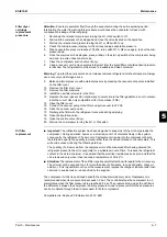
Oil filter replacement procedure:
1.
Shut down both compressors by turning the Q1 and Q2 switches to the off position.
2.
Turn the Q0 switch to off, wait for the circulation pump to turn off and open the general discon-
necting switch Q10 to cut off the machine's electrical power supply.
3.
Place a label on the handle of the general disconnecting switch in order to prevent accidental
start-up.
4.
Close the suction, discharge and liquid injection valves.
5.
Connect the recovery unit to the compressor and recover the refrigerant in a suitable and clean
container.
6.
Evacuate the refrigerant until the internal pressure has turned negative (compared to atmos-
pheric pressure). The amount of refrigerant dissolved in the oil is therefore reduced.
7.
Drain the oil in the compressor by opening the drain valve located under the oil separator.
8.
Remove the oil filter cover and the internal filter element.
9.
Replace the cover o-ring and internal sleeve. Do not lubricate the o-ring with mineral oil in order
not to contaminate the system.
10. Insert the new filter element.
11. Reposition the filter cover and tighten the screws. The screws must be tightened alternately and
progressively, setting the torque wrench at 60 Nm.
12. Charge the oil from the upper cover on the oil separator. Considering the high hygroscopy of
ester oil, it should be charged as quickly as possible. Do not expose ester oil to the atmosphere
for more than 15 minutes.
13. Close the oil charging cover.
14. Connect the vacuum pump and evacuate the compressor up to a vacuum of 230 Pa.
15. On reaching the above vacuum level, close the vacuum pump valve.
16. Open the suction, discharge and liquid injection system valves.
17. Disconnect the vacuum pump from the compressor.
18. Remove the warning label from the general disconnecting switch.
19. Close the general disconnecting switch Q10 to supply power to the machine.
20. Start the machine by following the start-up procedure described above.
Refrigerant charge
■
Important:
The units have been designed to operate with R-134a refrigerant. DO NOT USE
refrigerants other than R-134a.
■
Warning:
The addition or removal of refrigerant gas must be in accordance with current
regulations and laws.
■
Attention:
When refrigerant gas is added to or removed from the system, ensure proper water flow
through the evaporator for the entire charge/discharge time. Interrupting the water flow during this
procedure would cause the evaporator to freeze, with consequent breakage of internal piping.
Damage caused by freezing makes the warranty void.
■
Warning:
Removal of the refrigerant and replenishing operations must be performed by
technicians who are qualified to use the appropriate materials for this unit. Unsuitable maintenance
can result in uncontrolled losses in pressure and fluid. Do not disperse the refrigerant and
lubricating oil in the environment. Always be equipped with a suitable recovery system.
The units ship with a full refrigerant charge, but in some cases it may be necessary to replenish the
machine in the field.
■
Warning:
Always check the causes of a loss of refrigerant. Repair the system if necessary, then
recharge it.
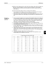
The machine can be replenished under any stable load condition (preferably between 70 and 100%)
and under any ambient temperature condition (preferably above 20°C). The machine should be kept
running for at least 5 minutes to allow the fan steps to stabilise and therefore condensation pressure.
The units have approximately 15% of condensation banks devoted to subcooling of the refrigerant
liquid. The subcooling value is equal to approx. 5-6°C (10-15°C for the economised machines). Once
the subcooling section has been completely filled, additional refrigerant will not increase system
efficiency. However, a small additional quantity of refrigerant (1÷2 kg) makes the system less
sensitive.
Summary of Contents for EWAD620-C17C-SL
Page 2: ......
Page 8: ...ESIE10 01 1 2 Part 1 System Outline 3 1 1 5 ...
Page 111: ...ESIE10 01 General Outline Part 1 System Outline 1 105 3 1 4 5 1 36 1 Power Compressor 1 2 ...
Page 112: ...General Outline ESIE10 01 1 106 Part 1 System Outline 3 1 1 4 5 1 36 2 Power Compressor 3 ...
Page 113: ...ESIE10 01 General Outline Part 1 System Outline 1 107 3 1 4 5 1 36 3 Kit Pumps ...
Page 122: ...General Outline ESIE10 01 1 116 Part 1 System Outline 3 1 1 4 5 1 36 12 Digital Inputs Board ...
Page 123: ...ESIE10 01 General Outline Part 1 System Outline 1 117 3 1 4 5 1 36 13 Digital Outputs Board ...
Page 124: ...General Outline ESIE10 01 1 118 Part 1 System Outline 3 1 1 4 5 1 36 14 Digital Outputs Board ...
Page 131: ...ESIE10 01 General Outline Part 1 System Outline 1 125 3 1 4 5 1 36 21 EEXV Compressor 1 ...
Page 134: ...General Outline ESIE10 01 1 128 Part 1 System Outline 3 1 1 4 5 1 36 24 EEXV Compressor 2 ...
Page 137: ...ESIE10 01 General Outline Part 1 System Outline 1 131 3 1 4 5 1 36 27 EEXV Compressor 3 ...
Page 138: ...General Outline ESIE10 01 1 132 Part 1 System Outline 3 1 1 4 5 1 36 28 Pumps Control ...
Page 139: ...ESIE10 01 General Outline Part 1 System Outline 1 133 3 1 4 5 1 36 29 Terminals M1 M2 ...
Page 140: ...General Outline ESIE10 01 1 134 Part 1 System Outline 3 1 1 4 5 1 36 30 Terminals M3 ...
Page 141: ...ESIE10 01 General Outline Part 1 System Outline 1 135 3 1 4 5 1 36 31 Terminals M5 MQ ...
Page 148: ...General Outline ESIE10 01 1 142 Part 1 System Outline 3 1 1 4 5 ...
Page 150: ...ESIE10 01 2 2 Part 2 Functional Description 3 1 2 5 ...
Page 170: ...The Digital Controller ESIE10 01 2 22 Part 2 Functional Description 3 1 2 4 5 ...
Page 200: ...Functional Control ESIE10 01 2 52 Part 2 Functional Description 3 1 2 4 5 ...
Page 202: ...ESIE10 01 3 2 Part 3 Troubleshooting 3 1 3 5 ...
Page 254: ...Alarms and Events ESIE10 01 3 54 Part 3 Troubleshooting 3 1 3 4 5 ...
Page 266: ...Controller Inputs and Outputs ESIE10 01 3 66 Part 3 Troubleshooting 3 1 3 4 5 ...
Page 280: ...ESIE10 01 4 2 Part 4 Commissioning and Test Run 3 1 4 5 ...
Page 286: ...Pre Test Run Checks ESIE10 01 4 8 Part 4 Commissioning and Test Run 3 1 4 5 ...
Page 289: ...ESIE10 01 Running Data Part 4 Commissioning and Test Run 4 11 3 4 5 1 ...
Page 290: ...Running Data ESIE10 01 4 12 Part 4 Commissioning and Test Run 3 1 4 5 ...


