Functional Control
ESIE10-01
2–26
Part 2 – Functional Description
3
1
2
4
5
2.2.2
Unit Mode Selection
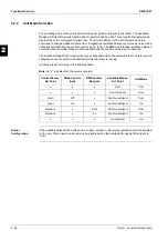
The operating mode of the unit is determined by set points and inputs to the chiller. The Available
Modes Set Point determines what modes of operation can be used. This set point also determines
whether the unit is configured for glycol use. The Control Source Set Point determines where a
command to change modes will come from. A digital input switches between cool mode and ice mode
if they are available and the control source is set to 'local'. The BMS mode request switches between
cool mode and ice mode if they are both available and the control source is set to 'network'.
The Available Modes Set Point should only be changeable when the unit switch is off. This is to avoid
changing modes of operation inadvertently while the chiller is running.
Unit Mode is set according to the following table.
Note:
An "x" indicates that the value is ignored.
Glycol
Configuration
If the Available Modes Set Point is set to an option ‘w/Glycol’, then glycol operation should be enabled
for the unit. Glycol operation should only be disabled when the Available Modes Set Point is set to
‘Cool’.
Control Source
Set Point
Mode Cool/Ice
Input
BMS Cool/Ice
Request
Available Modes
Set Point
Unit Mode
x
x
x
Cool
Cool
x
x
x
Cool w/Glycol
Cool
Local
Off
x
Cool/Ice w/Glycol
Cool
Local
On
x
Cool/Ice w/Glycol
Ice
Network
x
Cool
Cool/Ice w/Glycol
Cool
Network
x
Ice
Cool/Ice w/Glycol
Ice
x
x
x
Ice w/Glycol
Ice
Summary of Contents for EWAD620-C17C-SL
Page 2: ......
Page 8: ...ESIE10 01 1 2 Part 1 System Outline 3 1 1 5 ...
Page 111: ...ESIE10 01 General Outline Part 1 System Outline 1 105 3 1 4 5 1 36 1 Power Compressor 1 2 ...
Page 112: ...General Outline ESIE10 01 1 106 Part 1 System Outline 3 1 1 4 5 1 36 2 Power Compressor 3 ...
Page 113: ...ESIE10 01 General Outline Part 1 System Outline 1 107 3 1 4 5 1 36 3 Kit Pumps ...
Page 122: ...General Outline ESIE10 01 1 116 Part 1 System Outline 3 1 1 4 5 1 36 12 Digital Inputs Board ...
Page 123: ...ESIE10 01 General Outline Part 1 System Outline 1 117 3 1 4 5 1 36 13 Digital Outputs Board ...
Page 124: ...General Outline ESIE10 01 1 118 Part 1 System Outline 3 1 1 4 5 1 36 14 Digital Outputs Board ...
Page 131: ...ESIE10 01 General Outline Part 1 System Outline 1 125 3 1 4 5 1 36 21 EEXV Compressor 1 ...
Page 134: ...General Outline ESIE10 01 1 128 Part 1 System Outline 3 1 1 4 5 1 36 24 EEXV Compressor 2 ...
Page 137: ...ESIE10 01 General Outline Part 1 System Outline 1 131 3 1 4 5 1 36 27 EEXV Compressor 3 ...
Page 138: ...General Outline ESIE10 01 1 132 Part 1 System Outline 3 1 1 4 5 1 36 28 Pumps Control ...
Page 139: ...ESIE10 01 General Outline Part 1 System Outline 1 133 3 1 4 5 1 36 29 Terminals M1 M2 ...
Page 140: ...General Outline ESIE10 01 1 134 Part 1 System Outline 3 1 1 4 5 1 36 30 Terminals M3 ...
Page 141: ...ESIE10 01 General Outline Part 1 System Outline 1 135 3 1 4 5 1 36 31 Terminals M5 MQ ...
Page 148: ...General Outline ESIE10 01 1 142 Part 1 System Outline 3 1 1 4 5 ...
Page 150: ...ESIE10 01 2 2 Part 2 Functional Description 3 1 2 5 ...
Page 170: ...The Digital Controller ESIE10 01 2 22 Part 2 Functional Description 3 1 2 4 5 ...
Page 200: ...Functional Control ESIE10 01 2 52 Part 2 Functional Description 3 1 2 4 5 ...
Page 202: ...ESIE10 01 3 2 Part 3 Troubleshooting 3 1 3 5 ...
Page 254: ...Alarms and Events ESIE10 01 3 54 Part 3 Troubleshooting 3 1 3 4 5 ...
Page 266: ...Controller Inputs and Outputs ESIE10 01 3 66 Part 3 Troubleshooting 3 1 3 4 5 ...
Page 280: ...ESIE10 01 4 2 Part 4 Commissioning and Test Run 3 1 4 5 ...
Page 286: ...Pre Test Run Checks ESIE10 01 4 8 Part 4 Commissioning and Test Run 3 1 4 5 ...
Page 289: ...ESIE10 01 Running Data Part 4 Commissioning and Test Run 4 11 3 4 5 1 ...
Page 290: ...Running Data ESIE10 01 4 12 Part 4 Commissioning and Test Run 3 1 4 5 ...


