ESIE10-01
The Digital Controller
Part 2 – Functional Description
2–15
3
2
4
5
1
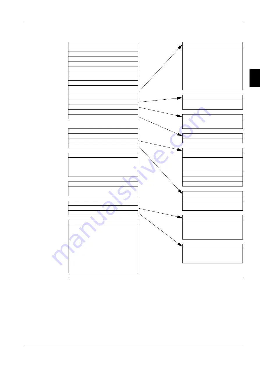
View/Set Unit
AWM Setup (view/set unit)
Status/Settings
>
Apply Changes
R/W
Set-Up
>
DHCP
R/W
Temperatures
>
Actual IP Address
R
Date/Time/Schedules
>
Actual Mask
R
Power Conservation
>
Actual Gateway
R
LON Setup
>
Given IP Address
R/W
BACnet IP Setup
>
Given Mask
R/W
BACnet MSTP Setup
>
Given Gateway
R/W
Modbus Setup
>
AWM BSP
R
AWM Setup
>
Design Conditions (view/set)
Design Conditions
>
Evap Entering Water Temp @
R
Alarm Limits
>
Evap Leaving Water Temp @
R
Menu Password
>
Alarm Limits (view/set unit)
Low Pressure Hold Setpoint
R
Low Pressure Unload Setpoint
R
View/Set Circuit
>
Menu Password (view/set)
Status/Settings
>
Password Disable
R/W
Compressor
>
Status/Settings (view/set)
Time Until Restart
Status Circuit 1
Compressor 1 Cycle Time
R
Circuit Status
R
Compressor 2 Cycle Time
R
Circuit Mode
R/W
Compressor 3 Cycle Time
R
Circuit Capacity
R
Compressor 4 Cycle Time
R
Status Circuit 2
>
Status Circuit 3
>
Scheduled Maintenance
Status Circuit 4
>
Next Maintenance Month/Year
R/W
Service Support Reference
R
Compressor (view/set circuit)
Compressor 1 Circuit 1
Alarms
>
Run Hours
R
Alarm Active
>
Number Of Starts
R
Alarm Log
>
Alarm Active (Alarms)
About This Chiller
Active Alarm 1
R
Model Number
R
...
R
G.O. Number
R
Active Alarm n
R
Unit Serial Number
R
Acknowledge All
R/W
Starter Model Number(s)
R
Starter Serial Number(s)
R
Alarm Log (Alarms)
Firmware Version
R
Alarm Entry 1
R
Application Version
R
...
R
Application GUID
R
Alarm Entry 25
R
HMI GUID
R
OBH GUID
R
Summary of Contents for EWAD620-C17C-SS
Page 2: ......
Page 8: ...ESIE10 01 1 2 Part 1 System Outline 3 1 1 5...
Page 111: ...ESIE10 01 General Outline Part 1 System Outline 1 105 3 1 4 5 1 36 1 Power Compressor 1 2...
Page 112: ...General Outline ESIE10 01 1 106 Part 1 System Outline 3 1 1 4 5 1 36 2 Power Compressor 3...
Page 113: ...ESIE10 01 General Outline Part 1 System Outline 1 107 3 1 4 5 1 36 3 Kit Pumps...
Page 122: ...General Outline ESIE10 01 1 116 Part 1 System Outline 3 1 1 4 5 1 36 12 Digital Inputs Board...
Page 123: ...ESIE10 01 General Outline Part 1 System Outline 1 117 3 1 4 5 1 36 13 Digital Outputs Board...
Page 124: ...General Outline ESIE10 01 1 118 Part 1 System Outline 3 1 1 4 5 1 36 14 Digital Outputs Board...
Page 127: ...ESIE10 01 General Outline Part 1 System Outline 1 121 3 1 4 5 1 36 17 Extension Control Fans 4...
Page 131: ...ESIE10 01 General Outline Part 1 System Outline 1 125 3 1 4 5 1 36 21 EEXV Compressor 1...
Page 134: ...General Outline ESIE10 01 1 128 Part 1 System Outline 3 1 1 4 5 1 36 24 EEXV Compressor 2...
Page 137: ...ESIE10 01 General Outline Part 1 System Outline 1 131 3 1 4 5 1 36 27 EEXV Compressor 3...
Page 138: ...General Outline ESIE10 01 1 132 Part 1 System Outline 3 1 1 4 5 1 36 28 Pumps Control...
Page 139: ...ESIE10 01 General Outline Part 1 System Outline 1 133 3 1 4 5 1 36 29 Terminals M1 M2...
Page 140: ...General Outline ESIE10 01 1 134 Part 1 System Outline 3 1 1 4 5 1 36 30 Terminals M3...
Page 141: ...ESIE10 01 General Outline Part 1 System Outline 1 135 3 1 4 5 1 36 31 Terminals M5 MQ...
Page 148: ...General Outline ESIE10 01 1 142 Part 1 System Outline 3 1 1 4 5...
Page 150: ...ESIE10 01 2 2 Part 2 Functional Description 3 1 2 5...
Page 170: ...The Digital Controller ESIE10 01 2 22 Part 2 Functional Description 3 1 2 4 5...
Page 200: ...Functional Control ESIE10 01 2 52 Part 2 Functional Description 3 1 2 4 5...
Page 202: ...ESIE10 01 3 2 Part 3 Troubleshooting 3 1 3 5...
Page 254: ...Alarms and Events ESIE10 01 3 54 Part 3 Troubleshooting 3 1 3 4 5...
Page 266: ...Controller Inputs and Outputs ESIE10 01 3 66 Part 3 Troubleshooting 3 1 3 4 5...
Page 280: ...ESIE10 01 4 2 Part 4 Commissioning and Test Run 3 1 4 5...
Page 286: ...Pre Test Run Checks ESIE10 01 4 8 Part 4 Commissioning and Test Run 3 1 4 5...
Page 289: ...ESIE10 01 Running Data Part 4 Commissioning and Test Run 4 11 3 4 5 1...
Page 290: ...Running Data ESIE10 01 4 12 Part 4 Commissioning and Test Run 3 1 4 5...


